Welcome to the Keilton+autani App Guide
Select a learning path below to get started with commissioning your lighting network.
🚀 Getting Started
New to the system? Start here to understand the basics.
🏢 Zones & Infrastructure
Learn how to manage the fundamental building blocks of your network.
💡 Light & Sensor Configuration
Learn how to add and configure your devices.
01 Getting Started
Getting Started & System Overview
Video Tutorial
Watch the companion video Chapter 1: Getting Started and App Navigation for a visual walkthrough of these steps.
Overview
The Keilton+autani system provides intelligent control of commercial lighting through advanced Bluetooth Low Energy Mesh protocols (versions 4.2 and 5.0). Developed in the USA by LiteTrace, this system delivers industry-leading performance, security, and energy efficiency with wireless communication up to 100 feet or more between devices.
This article introduces the system's capabilities, explains key concepts, and identifies the main components you'll work with.
System Capabilities
With the Keilton+autani system, you can:
- Commission wirelessly — Set up your entire lighting network directly from a mobile device without requiring internet access or gateways
- Control flexibly — Manage individual fixtures or create customized lighting groups
- Create scenes — Design preset lighting configurations for different activities and environments
- Automate operations — Set schedules based on time, occupancy, and ambient light
- Monitor energy — Track usage and optimize efficiency across your facility
Understanding LLLC
Luminaire-Level Lighting Control (LLLC) is the foundation of this system. LLLC means each individual light fixture is equipped with its own control device or integrated control system, allowing for independent control and management of each fixture.
LLLC Capabilities
Each LLLC luminaire can:
- Detect human movement using integrated motion sensors
- Measure ambient light levels using photosensors
- Automatically respond by turning on, off, or dimming based on conditions
- Operate independently without requiring a central controller
This approach maximizes energy efficiency because each fixture responds to its immediate environment rather than operating on a fixed schedule.
System Components
The Keilton+autani system consists of four main component types:
1. Networked Controllers and Sensors
Controllers connect to lighting fixtures while sensors detect occupancy and ambient light. Together, they create an intelligent lighting environment that responds automatically to changing conditions.
2. Wall Switches
Wireless controls that can be programmed to manage individual lights, groups, or activate custom scenes. These switches do not require complex wiring for installation.
3. The Keilton+autani Mobile App
The central interface for commissioning, configuring, and controlling all system components. Key features include:
- Works without gateways or internet access
- Uses data encryption for mesh network security
- Stores configuration in encrypted QR codes
- Available for iOS and Android devices
4. QR Codes
Encrypted codes that control access to each network device. QR codes enable secure sharing of zone access with authorized users while maintaining system security.
Bluetooth Mesh Networking
The system uses Bluetooth mesh networking, where each device can relay signals to other devices. This provides several advantages:
| Benefit | Description |
|---|---|
| Extended range | Signals hop between devices, reaching far beyond single Bluetooth range |
| Self-healing | If one device goes offline, the mesh routes around it automatically |
| Resilient connectivity | The network maintains operation even with device failures |
| No central hub required | Devices communicate directly without a gateway |
Certifications & Compliance
LiteTrace certifications ensure the Keilton+autani system meets the highest industry standards:
- UL 1376 Verification — First Chinese manufacturer to receive security capabilities verification
- Full-Stack R&D — First to achieve in-house development for networked sensors and controllers
- DLC NLC5 Listed — One of the first systems listed to DLC's Networked Lighting Controls standard
Data Persistence
All settings—including sensor parameters, group configurations, scene definitions, and schedules—are saved directly on individual luminaire controllers. This means:
- The system continues operating correctly after power outages
- No network connection is required for normal operation
- Settings persist without cloud dependency
Before You Begin
For the best experience with the Keilton+autani system, ensure:
- Your mobile device has Bluetooth 4.2 or later
- Camera access is enabled for QR code scanning
- Lighting fixtures are installed and powered
- You plan to use a single device during commissioning
Related Articles
- System Capacity Limits
- Downloading and Navigating the App
- Understanding the Commissioning Process
- Creating and Managing Zones
Based on Keilton+autani App User Guide v9.7
System Capacity Limits
Quick Reference
This page consolidates all platform capacity limits for the Keilton+autani NLC system in one place. Individual limits are also noted in their respective topic articles throughout this guide.
Overview
The Keilton+autani platform enforces specific capacity limits to ensure reliable wireless communication and system performance. Understanding these limits is essential when planning your installation, especially for larger facilities that may require multiple zones.
Capacity Limits Reference
| Category | Limit | What Happens If Exceeded |
|---|---|---|
| Online Nodes | Up to 100 online nodes per zone | Divide into additional zones |
| Luminaire / Group | A light can belong to up to 20 groups | Adding a 21st group removes the light from the first group automatically |
| Scenes (per light) | Up to 32 scenes per light | Adding a 33rd scene removes the first scene from that light |
| Scenes (per zone) | Up to 66 scenes per zone | Includes Quick Create Scenes and scenes from template creation |
| Schedules | Up to 32 schedules per zone | Additional schedules cannot be created |
| Switches | Up to 32 switches per zone | Area sensors count toward this limit (see details below) |
| Zones | Unlimited zones per app on a mobile phone | No restriction |
| Data Persistence | All settings saved on individual luminaire controllers | System continues operating after power outages or without network connection |
Online Node Details
Online nodes include the following device types:
- LLLC sensors — IFS108, EFS106, EFS104, etc.
- Controllers — PPA102S, PPA104S, FA102, WF20R, PPA109, etc.
- Area sensors — CS107S, CS107D, etc.
- Sensor switches — IWS102, etc.
- Dongles and gateways — CR01, CR02, CR04, BG01, etc.
Exclusions from the 100-Node Limit
Wall switches and battery-powered BCS107 sensors are not counted toward the 100 online node limit. However, they do count toward other limits (see Switch details below).
Zone Sizing Guidelines
When dividing a site into zones, follow these physical constraints to maintain reliable wireless coverage:
| Guideline | Recommendation |
|---|---|
| Maximum radius | 150 feet |
| Maximum area | 9,000 square feet |
| Signal obstructions | Avoid concrete walls or large metal objects within a zone |
| Node count | No more than 100 online nodes per zone |
Switch Limit Details
The 32-switch limit per zone is calculated separately from the 100-node light limit. Adding switches to a zone does not reduce the available online node count.
Devices that count toward the 32-switch limit:
- Battery-powered switches — WP1013, WP1018, WP1025, etc.
- Line voltage switches — WP1013S, WP1017S, WP1018S
- Area sensors — CS107D, CS107S, BCS107
Tip
Because some area sensors count toward the switch limit (32), plan your sensor placement with both limits in mind.
Planning with Capacity Limits
Control Intent Narrative (CIN) and Sequences of Operations (SOO)
Before purchasing and installing an NLC system, facility managers should define owner requirements and control system goals in a design document called the Control Intent Narrative (CIN) and Sequences of Operations (SOO). Two industry standards that can assist in creating these documents are:
- ANSI/IES LP-6-20, Lighting Control Systems: Properties, Selection, and Specification
- ANSI/IES LP-16-22, Documenting Control Intent Narratives and Sequences of Operations
At a minimum, the CIN and SOO should contain:
- A floor plan and the functions of each zone
- Each light's model number, quantity, and position
- Zone definitions based on lighting functions, observing the 100-node and physical size limits above
- Group number, group name, scene number, scene name, and approximate scene design for each zone
- Switch type and number, as well as the function of buttons for each zone
Related Articles
- System Overview
- Creating and Managing Zones
- Adding Lights to the Network
- Creating and Managing Groups
- Creating Scenes
- Adding and Managing Switches
- Creating Schedules
Based on Keilton+autani App User Guide v9.8
Understanding the Commissioning Process
Overview
Commissioning is the process of setting up and configuring your lighting network. This transforms individual lighting fixtures into an intelligent, coordinated system. This article explains the recommended workflow, best practices, and critical rules for successful commissioning.
What Happens During Commissioning
During the commissioning process, you will:
- Create zones to organize your installation
- Add lights to each zone
- Organize lights into groups
- Create scenes for different activities
- Configure sensor parameters
- Assign switches to control lights
- Set up schedules for automated operation
All settings are saved directly to each luminaire controller, ensuring the system continues operating correctly after power outages or without network connection.
Recommended Workflow
Follow this four-phase approach for efficient commissioning:
Phase 1: Preparation
Complete these tasks before arriving on site:
- Define the Control Intent Narrative (CIN) and Sequence of Operations (SOO)
- Document zone functions, light positions, and quantities
- Pre-define group names, scene names, and switch assignments
- Verify all lights are installed
- Test power for each fixture
Phase 2: Lights, Groups, and Scenes
Configure the basic structure of your lighting network:
- Create zones and generate QR codes
- Connect lights to the app
- Organize lights into groups
- Create scene settings
- Add and configure switch controls
- Set timers and schedules
Phase 3: Sensor Configuration
Fine-tune automatic behavior:
- Set sensor parameters (time delays, sensitivity, dim levels)
- Configure light linkage levels between grouped fixtures
- Set auto light levels using calibration or manual settings
Phase 4: Project Delivery
Complete the handoff:
- Verify all configurations are working correctly
- Sync all data to the cloud
- Share QR codes with the building owner or facility manager
- Provide both Admin and User level access as appropriate
Critical Best Practices
Use Only One Device
Never use more than one mobile device during commissioning. Using multiple devices simultaneously can cause:
- Data corruption
- Duplicate light addresses
- Unexpected system behavior
Designate one device as the commissioning tool and use it exclusively throughout the process.
Limit Powered Lights
Do not power more than 100 factory-setting lights at once. Having too many lights broadcasting signals can:
- Deteriorate commissioning performance
- Cause wireless communication interference
- Result in failed connections
Power off lights that are not in your current zone before continuing.
Sync Before Sharing
Always sync your data before sharing QR codes. The app saves commissioning data to the cloud in the background, but you should verify synchronization:
- A red dot next to the zone name indicates unsynced data
- Navigate to More → Force Sync to manually sync
- Never share QR codes while the red dot is displayed
Pre-Plan Your Installation
Creating zones, groups, and scenes before arriving on site significantly reduces commissioning time. Your Control Intent Narrative should include:
| Element | Details to Document |
|---|---|
| Floor plan | Zone boundaries and functions |
| Lights | Model numbers, quantities, positions |
| Zone definitions | Max 100 nodes, < 150 ft radius, < 9,000 sq ft |
| Groups | Names and member lights |
| Scenes | Names and light level designs |
| Switches | Types, quantities, button assignments |
Handling Poor Connectivity
If you have poor internet connectivity on site, you can still complete commissioning:
- Turn off WiFi or enable airplane mode on your device
- Complete all commissioning work offline
- When finished, connect to a reliable internet connection
- Navigate to More → Force Sync to upload your data
Important
Do not share QR codes until after you have successfully synced.
Industry Standards Reference
Two industry standards can assist in creating your Control Intent Narrative and Sequence of Operations:
- ANSI/IES LP-6-20: Lighting Control Systems: Properties, Selection, and Specification
- ANSI/IES LP-16-22: Documenting Control Intent Narratives and Sequences of Operations
Common Issues and Solutions
| Issue | Solution |
|---|---|
| Lights not appearing in scan | Verify power, reduce total powered lights, move closer |
| Red dot won't clear | Check internet connection, try Force Sync again |
| Data conflicts between users | Ensure only one device is used for commissioning |
| Slow commissioning performance | Power off lights not in current zone |
| Can't add lights to zone | Verify zone has fewer than 100 nodes |
Quick Reference: Commissioning Phases
| Phase | Key Activities |
|---|---|
| 1. Preparation | Define CIN/SOO, verify installations, pre-plan |
| 2. Lights/Groups/Scenes | Create zones, add lights, organize, configure |
| 3. Sensor Configuration | Set parameters, configure linkage, calibrate |
| 4. Project Delivery | Verify, sync, share QR codes |
Related Articles
Based on Keilton+autani App User Guide v9.7
02 Zones & QR Codes
Creating and Managing Zones
Video Tutorial
Watch the companion video Chapter 2: Zones and QR Codes for a visual walkthrough of these steps.
Overview
Zones are the foundation of your Keilton+autani lighting network. A zone is a defined area containing lights, switches, sensors, and other devices that are managed together. Each zone operates independently with its own settings and QR codes.
Before you can add lights or configure your system, you must first create at least one zone.
Zone Capacity and Planning
Each zone supports up to 100 online nodes, including: - LLLC sensors (IFS108, EFS106, EFS104, etc.) - Controllers (PPA102S, PPA104S, FA102, WF20R, etc.) - Area sensors (CS107S, CS107D, etc.) - Dongles and gateways (CR01, CR02, CR04, BG01, etc.)
Note
Wall switches and battery-powered sensors (BCS107) do not count toward the 100-node limit.
See Also
For a complete breakdown of all platform capacity limits — including scenes, schedules, switches, and groups — see System Capacity Limits.
Planning Recommendations
| Guideline | Details |
|---|---|
| Zone by function | Create separate zones for different areas (offices, hallways, conference rooms) |
| Physical barriers | Avoid placing devices across concrete walls or large metal objects that block wireless signals |
| Size limits | Keep zones within a 150-foot radius and under 9,000 square feet |
| Pre-plan | Create zones and define group/scene names before arriving on site |
Creating a Zone
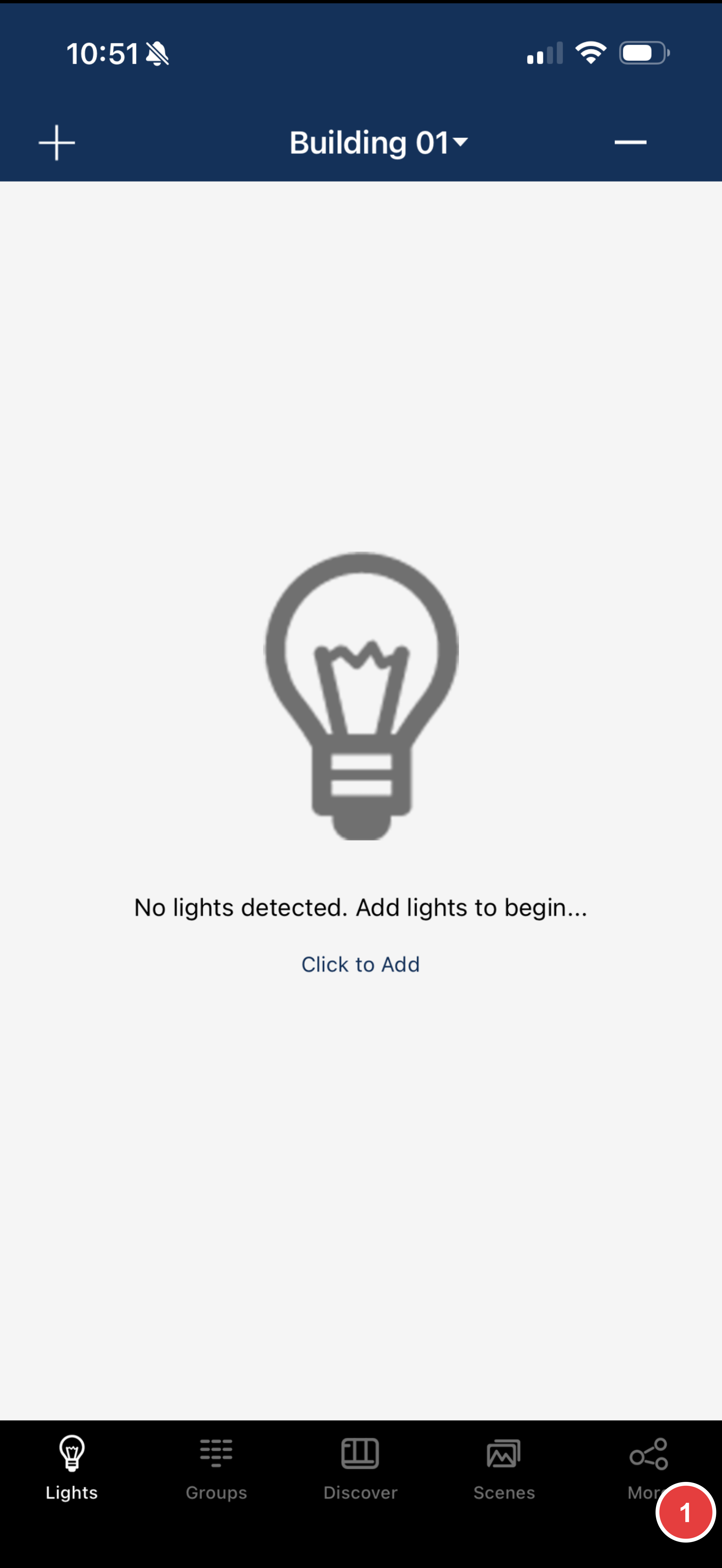
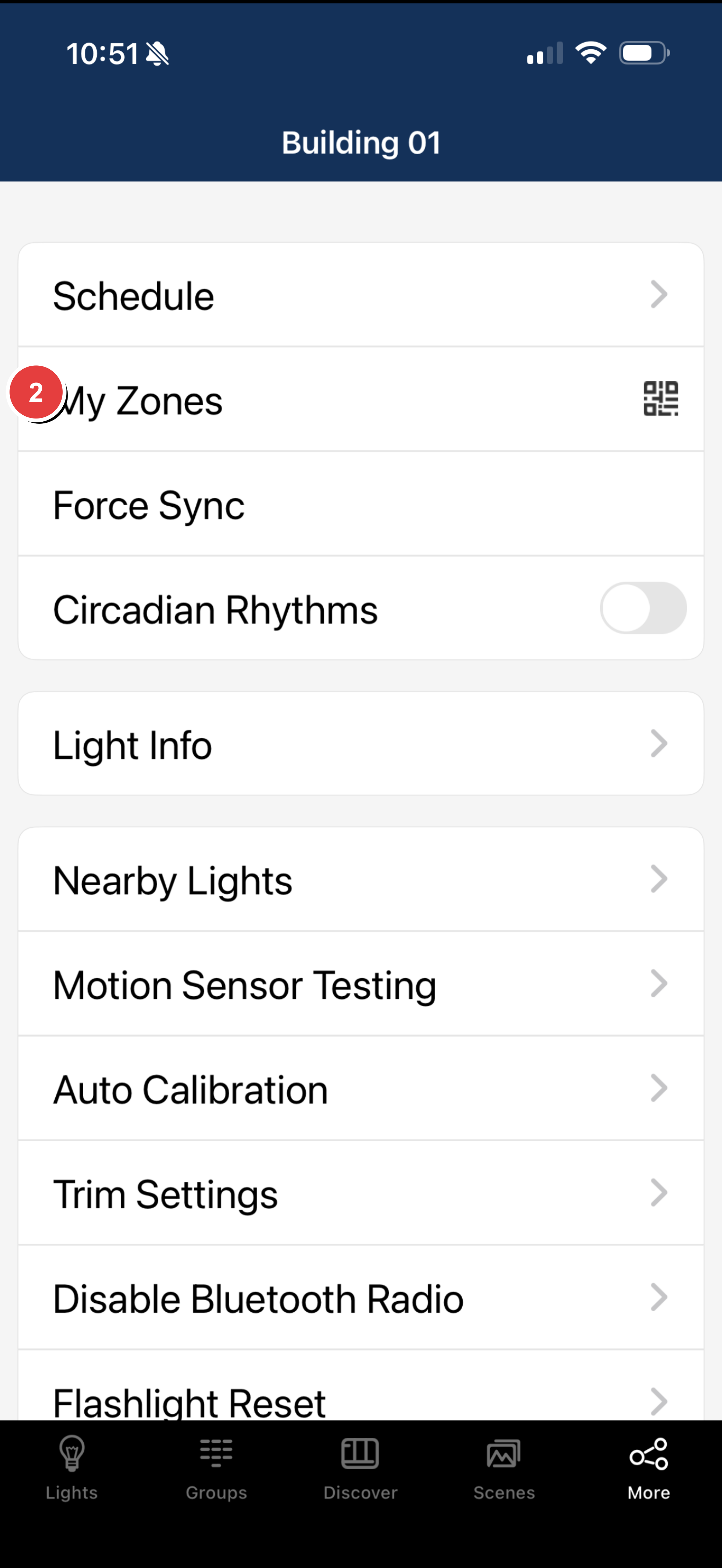
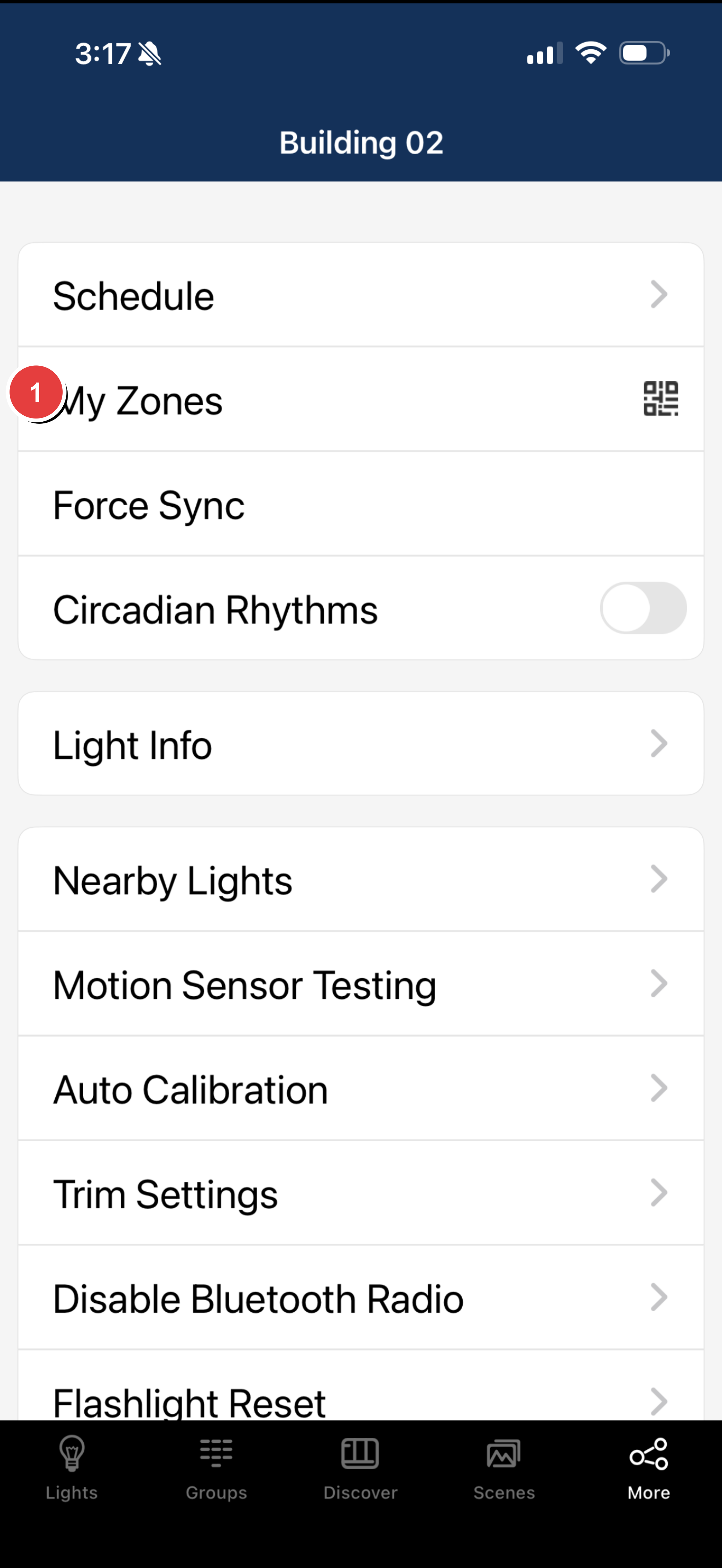
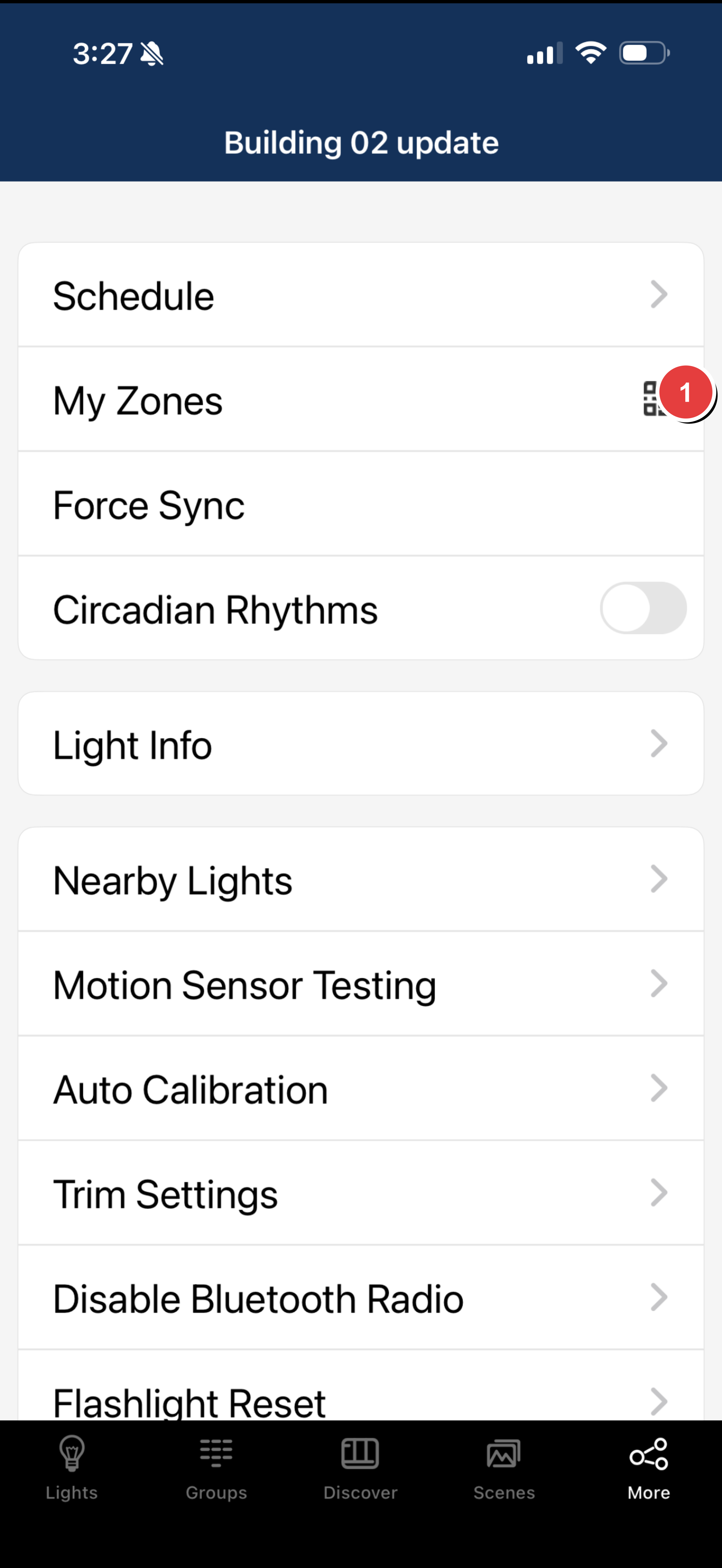
- Open the Keilton+autani app and tap the More tab at the bottom of the screen.
- Select My Zones.
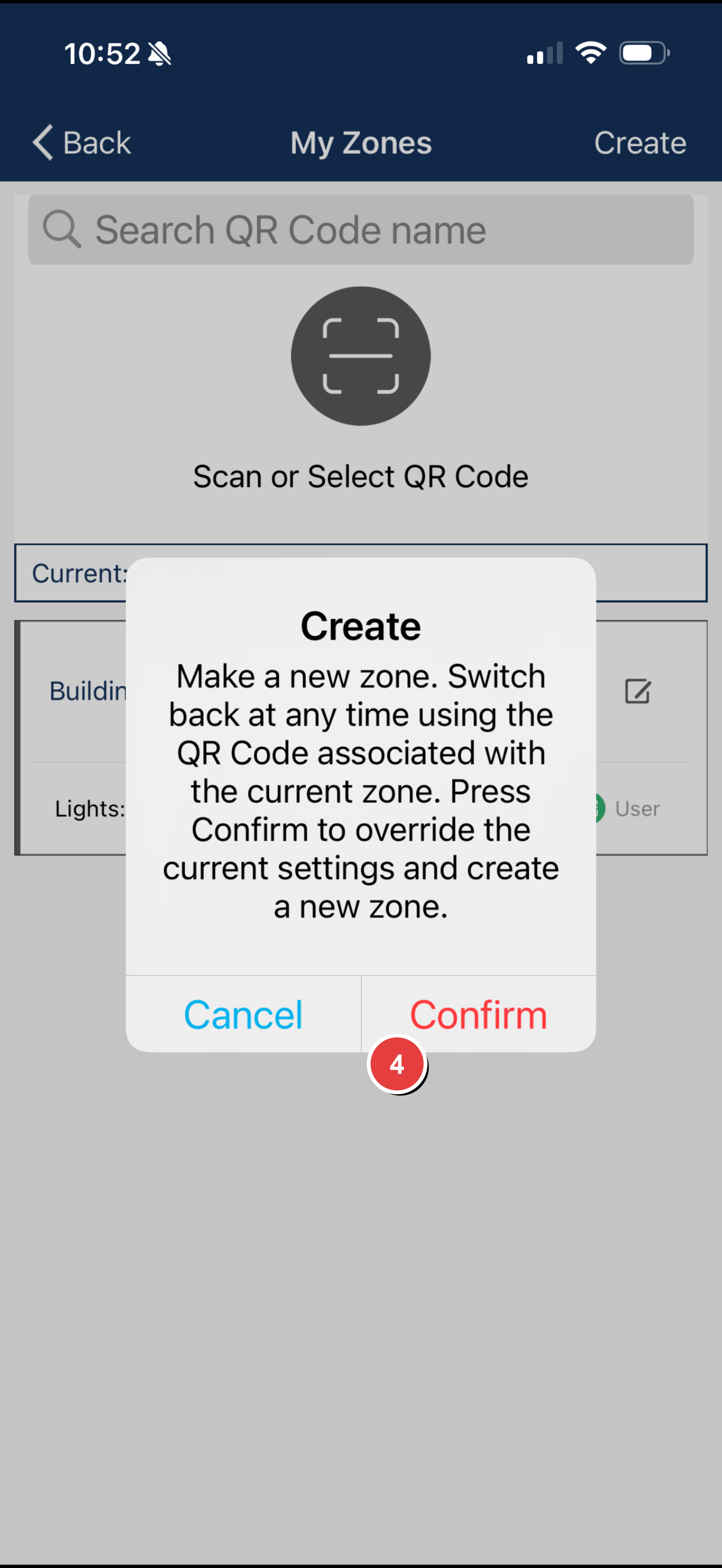
- Tap Create in the top-right corner.
- Tap Confirm in the dialog that appears.
- Enter a descriptive name for your zone (e.g., "Building A - Second Floor" or "Warehouse East Wing").
- Tap OK to save.
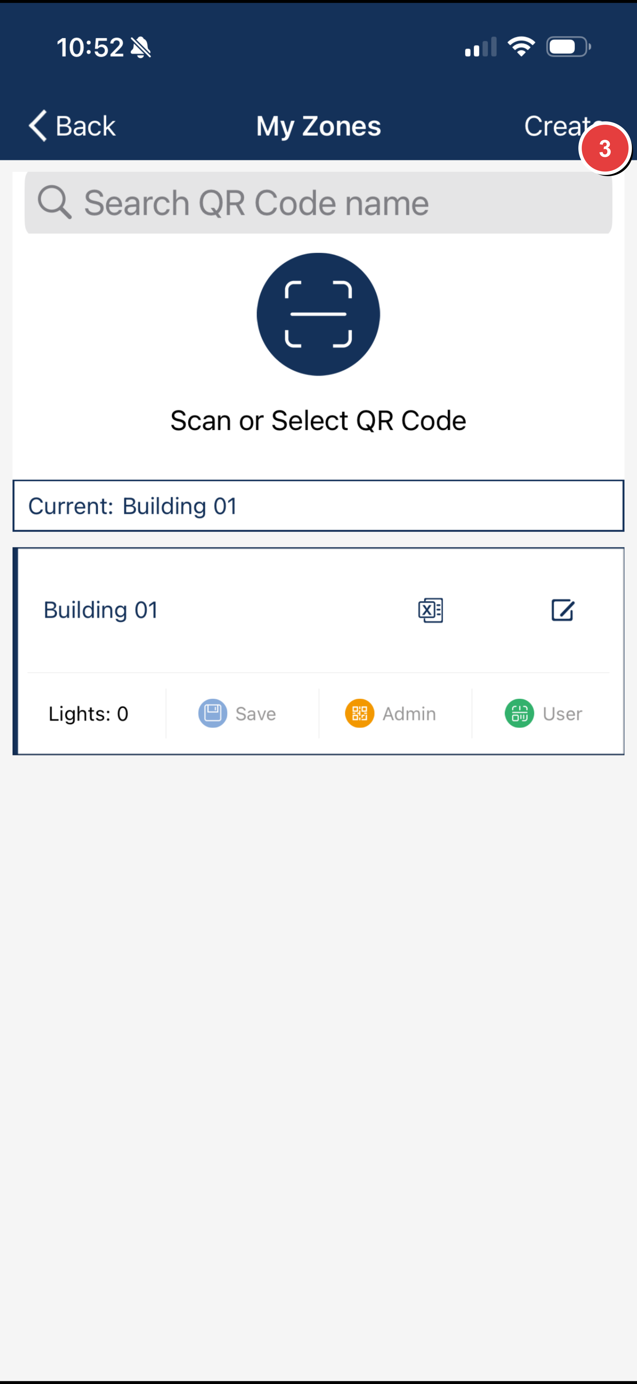
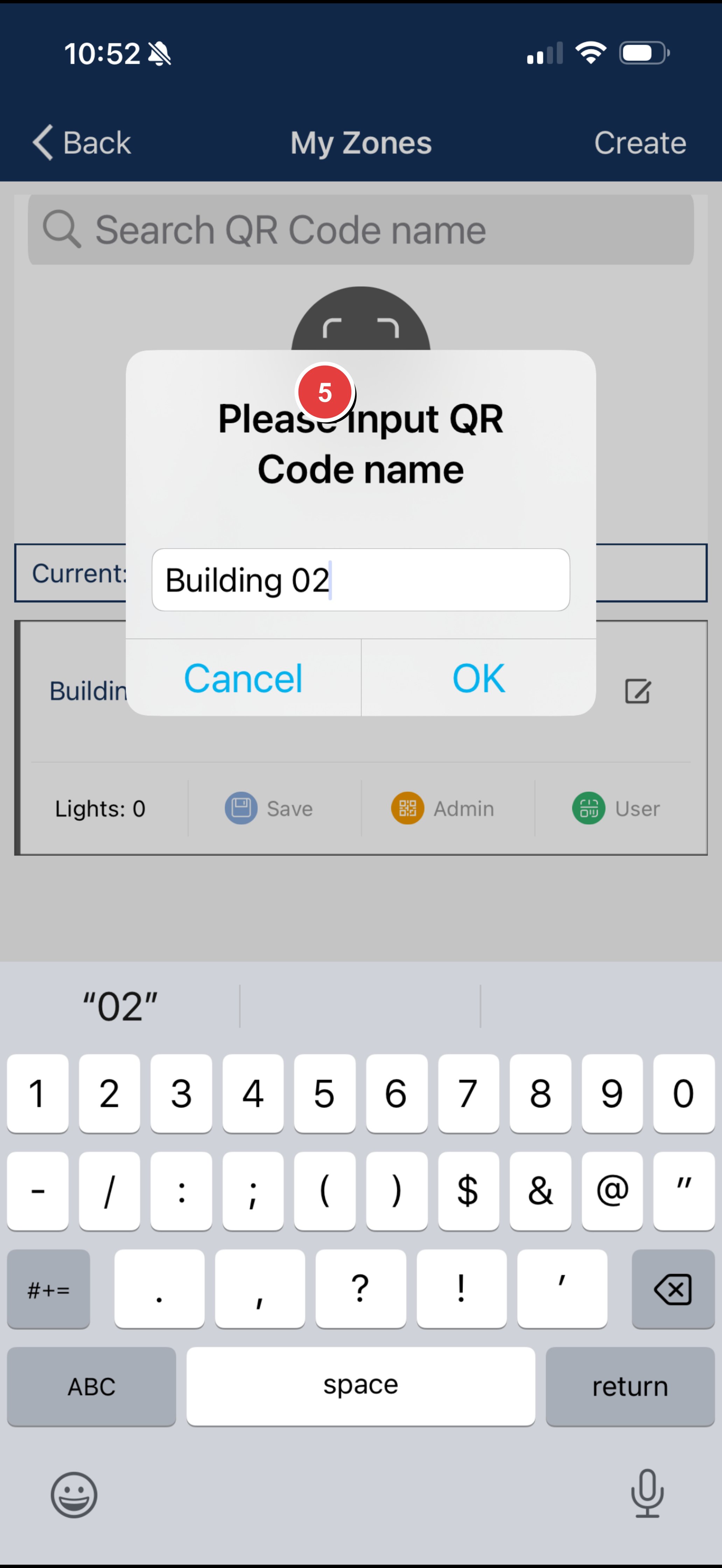
Your new zone now appears in the My Zones list. The app automatically generates two QR codes for this zone—one for Admin access and one for User access.
Tip: Use clear, descriptive names that include building, floor, or area identifiers for easy identification later.
Renaming a Zone
- Navigate to More → My Zones.
- Locate the zone you want to rename.
- Tap the edit button (pencil icon) to the right of the zone name.
- Enter the new name in the prompt.
- Tap OK to save.
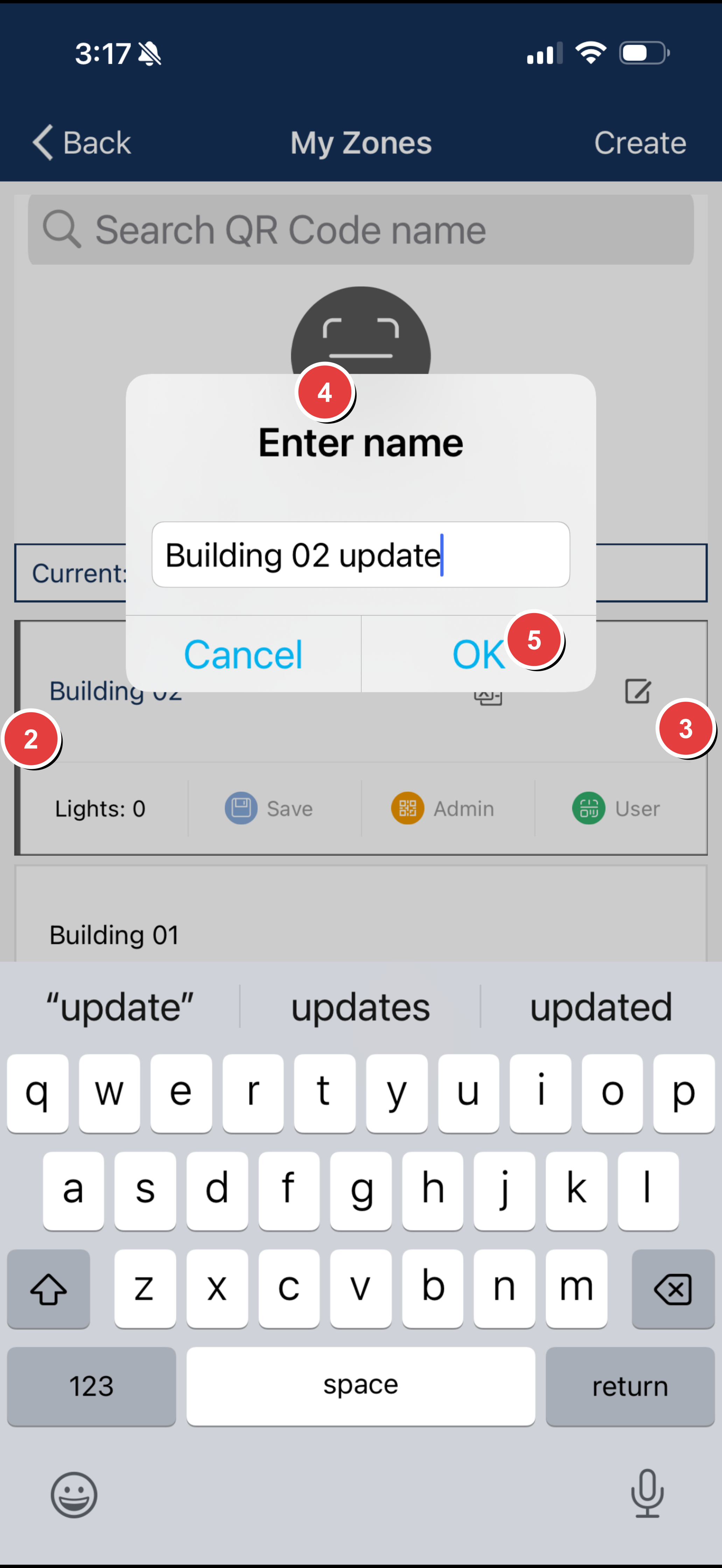
The zone name updates immediately across the app and its associated QR codes.
Deleting a Zone
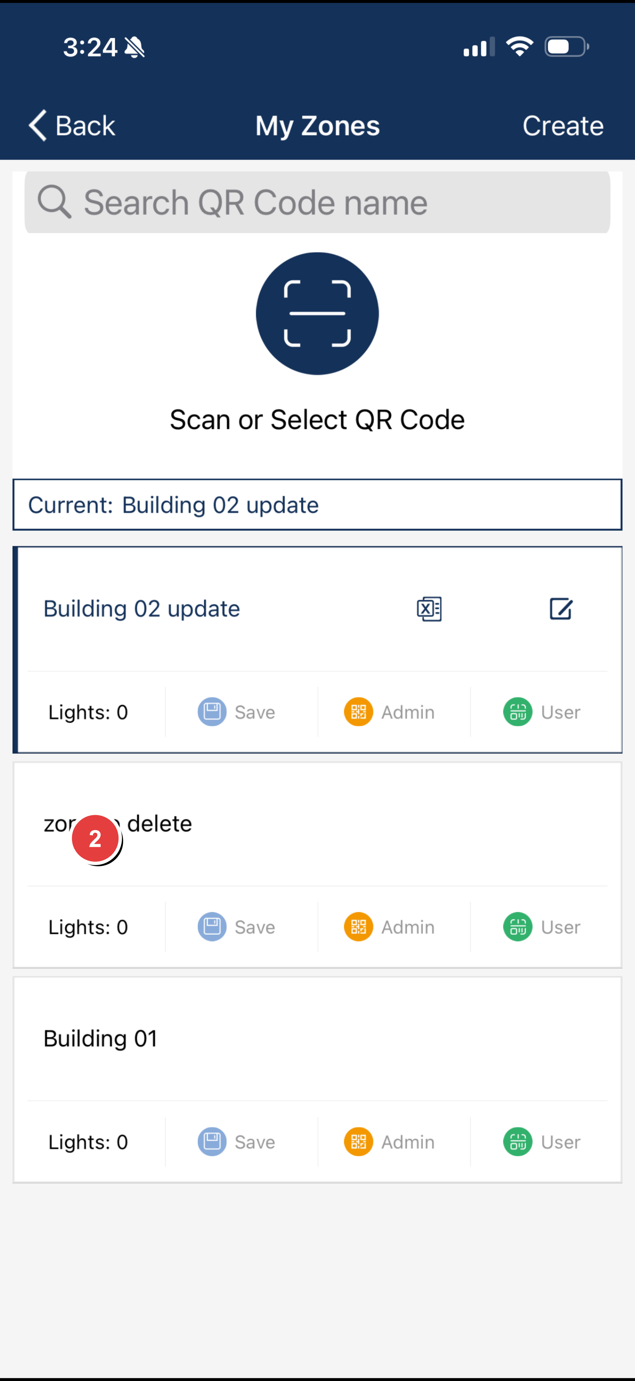
- Navigate to More → My Zones.
- Find the zone you want to delete.
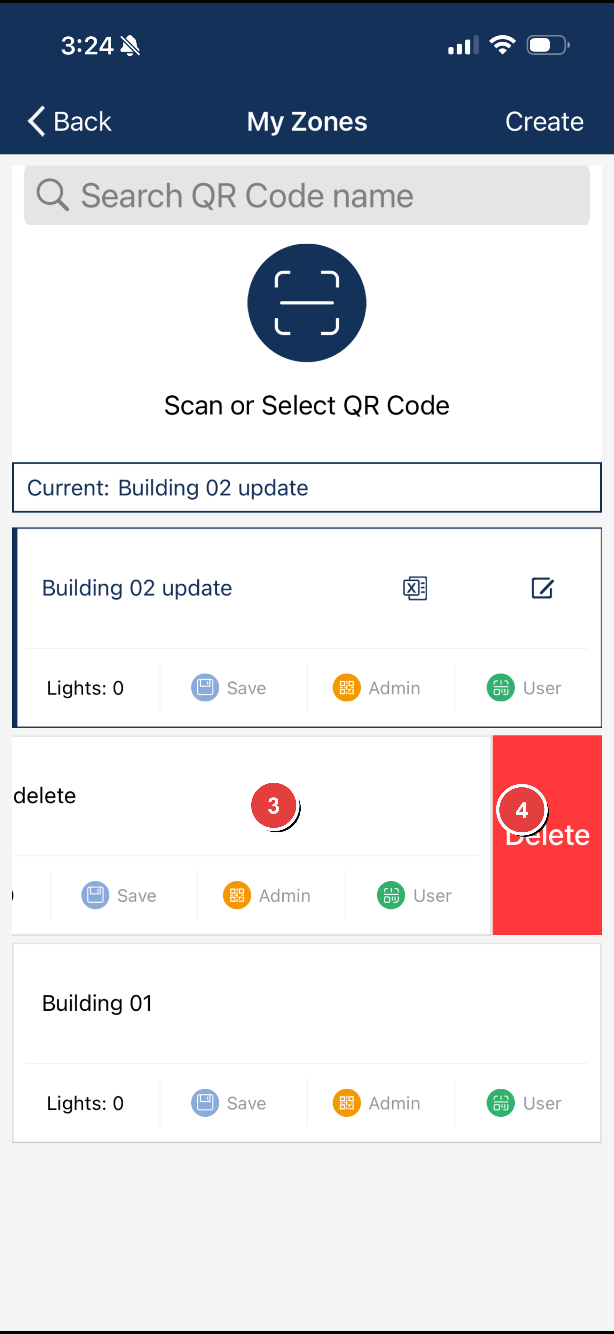
- Swipe from right to left across the zone's row.
- Tap the red Delete button that appears.
- Tap Delete again to confirm.
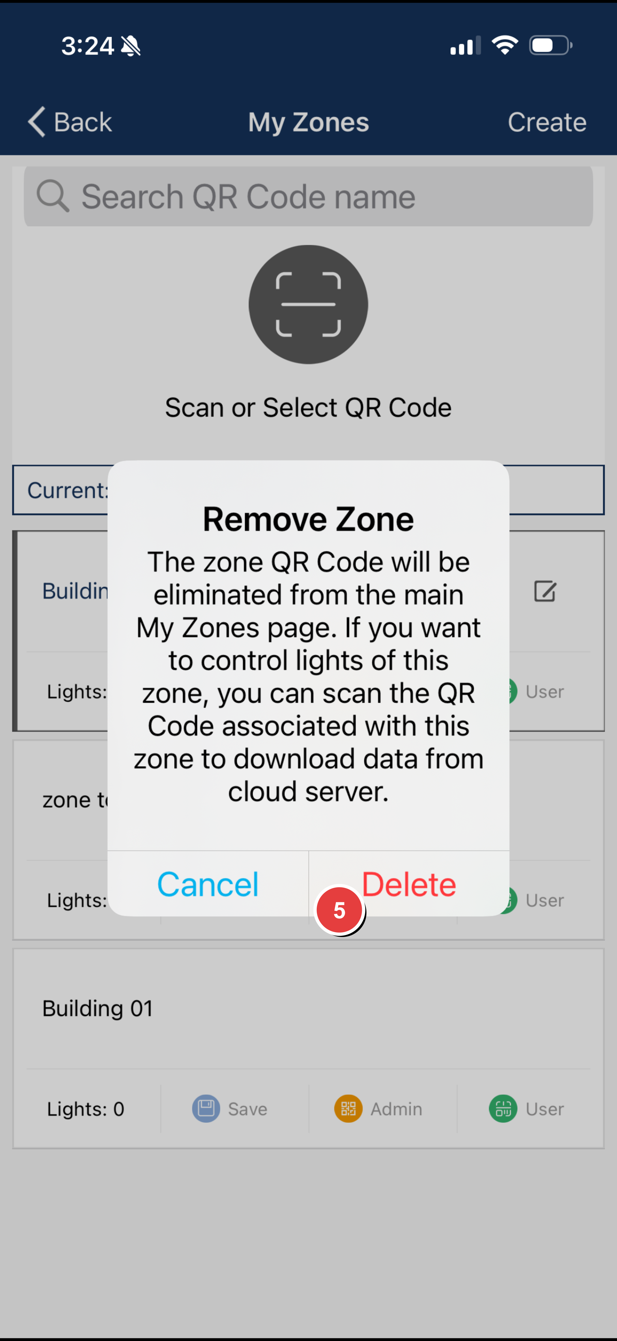
Important
You cannot delete the zone you are currently active in. Switch to a different zone first before attempting to delete.
Sync Status Indicator
A red dot next to a zone name indicates that data needs to sync to the cloud. Before sharing QR codes or switching devices, ensure all data is synced:
- Navigate to More.
- Select Force Sync to manually sync your data.
- Wait for the sync to complete (red dot will disappear).
Quick Reference
| Task | Steps |
|---|---|
| Create Zone | More → My Zones → Create → Confirm → Enter name → OK |
| Rename Zone | More → My Zones → Edit button → Enter name → OK |
| Delete Zone | More → My Zones → Swipe left → Delete → Confirm |
| Force Sync | More → Force Sync |
Related Articles
- System Capacity Limits
- Working with QR Codes (Admin vs User)
- Saving and Sharing QR Codes
- Adding Lights to Your Network
Based on Keilton+autani App User Guide v9.7
Working with QR Codes (Admin vs User)
Overview
QR codes are the key to accessing and controlling your Keilton+autani lighting zones. Every zone you create automatically generates two QR codes—one for Admin access and one for User access. These codes contain encrypted configuration data that controls access to all devices in the zone.
Think of QR codes as encrypted keys: without the correct code, no one can access or control your lighting network. This provides security without requiring passwords or user accounts.
Admin vs User Access Levels
The two QR codes provide different levels of access to your lighting system.
Admin Access
The Admin QR code provides full control over the zone. With Admin access, you can:
- Add and delete lights, switches, and sensors
- Create, modify, and delete groups
- Configure scenes and schedules
- Adjust all sensor settings and parameters
- Change trim settings and advanced configurations
- Share both Admin and User QR codes with others
User Access
The User QR code provides operational control only. With User access, you can:
- Turn lights on and off
- Dim lights and adjust brightness
- Adjust color temperature (on supported fixtures)
- Activate scenes
- Control lights within groups
With User access, you cannot:
- Add, delete, or reconfigure any devices
- Create or modify groups, scenes, or schedules
- Change sensor settings or parameters
- Share Admin access (only Admin code holders can do this)
Access Level Comparison
| Feature | Admin | User |
|---|---|---|
| Turn lights on/off | ✓ | ✓ |
| Dim lights | ✓ | ✓ |
| Adjust color temperature | ✓ | ✓ |
| Activate scenes | ✓ | ✓ |
| Control groups | ✓ | ✓ |
| Add/delete lights | ✓ | ✗ |
| Create/edit groups | ✓ | ✗ |
| Configure scenes | ✓ | ✗ |
| Adjust sensor settings | ✓ | ✗ |
| Create/edit schedules | ✓ | ✗ |
| Modify trim settings | ✓ | ✗ |
| Share Admin QR code | ✓ | ✗ |
| Share User QR code | ✓ | ✗ |
Recommended Access by Role
| Role | Recommended Access |
|---|---|
| Installer / Commissioning Agent | Admin |
| Facility Manager | Admin |
| Building Owner | Admin |
| IT Administrator | Admin |
| Office Manager | User or Admin (based on needs) |
| Building Occupants | User |
| Cleaning / Maintenance Staff | User |
| Security Personnel | User |
Scanning a QR Code
To access a zone using a QR code:
- Open the app and navigate to More → My Zones.
- Tap Scan or Select QR code at the top of the list.
- Your camera will activate. Center the QR code within the frame on your screen.
- The app automatically scans and processes the code.
- Once scanned, the zone appears in your My Zones list with the corresponding access level.
Scanning from a Saved Image
If you have a QR code saved as an image on your device:
- Navigate to More → My Zones.
- Tap Scan or Select QR code.
- Tap the Album button.
- Navigate to and select the saved QR code image.
- The app reads the code and adds the zone to your list.
Important Considerations
-
Protect Admin codes: Anyone with the Admin QR code has full system access. Only share Admin codes with trusted personnel.
-
Access cannot be revoked: Once someone has scanned an Admin code, you cannot revoke their access without resetting the entire zone.
-
One zone per code: Each QR code is tied to a specific zone. You need separate codes for each zone.
-
User limitations protect your system: Users cannot accidentally (or intentionally) reconfigure your lighting system.
Related Articles
Based on Keilton+autani App User Guide v9.7
Saving and Sharing QR Codes
Overview
Once you've created zones, you'll want to save and share the associated QR codes. This article covers how to save QR codes to your phone, share them with team members, restore zone access on a new device, and export commission reports.
Saving QR Codes to Your Photo Library
Saving QR codes to your phone ensures you have a backup and makes sharing easier.
Prerequisites
Before saving QR codes, ensure the app has permission to access your photos: - iOS: Settings → Keilton → Photos → Allow access - Android: Settings → Apps → Keilton → Permissions → Storage/Photos
Steps to Save
- Navigate to More → My Zones.
- Select the zone whose QR code you want to save.
- Tap the Save button located beneath the zone name.
- The QR code saves automatically to a folder called MyQRCode in your photo album.
You can save both Admin and User QR codes. Repeat the process for each code type you need to save.
Tip: Save both Admin and User codes for each zone as a backup. Consider emailing copies to yourself for additional security.
Sharing QR Codes
There are two primary methods for sharing QR codes with others.
Method 1: Direct Scanning
- Navigate to More → My Zones.
- Select the zone you want to share.
- Tap either Admin or User to display that QR code.
- Have the other person open their Keilton+autani app.
- They navigate to More → My Zones → Scan or Select QR code.
- They scan the code displayed on your screen.
This method is ideal for in-person handoffs where both parties are present.
Method 2: Sending a Saved Image
- Open your photo library and navigate to the MyQRCode folder.
- Select the QR code you want to share.
- Use your phone's share function to send via email, text message, or other messaging app.
- The recipient saves the image and scans it using the Album option in the app.
This method works well for remote team members or when documentation is needed.
Critical: Sync Before Sharing
Before sharing any QR code, ensure your zone data has synced to the cloud.
A red dot next to the zone name indicates unsynced data. If you share a code before syncing, the recipient may not receive the complete configuration.
To Force Sync:
- Navigate to More.
- Tap Force Sync.
- Wait for the sync to complete (the red dot will disappear).
- You may now safely share the QR code.
Warning: Never share QR codes while a red dot is displayed. The recipient's access may be incomplete or non-functional.
Restoring Zone Access
If you need to restore access to a zone—on a new phone, after reinstalling the app, or on a secondary device—you can do so by scanning a saved QR code.
Steps to Restore
- Open the app and navigate to More → My Zones.
- Tap Scan or Select QR code.
- Either:
- Scan a printed or displayed QR code, or
- Tap Album and select a saved QR code image
- The app adds the zone to your list with all lights, groups, and settings intact.
Your access level (Admin or User) matches the type of code you scanned.
Exporting Commission Reports
You can export a detailed commission report for documentation and project handoff.
Steps to Export
- Navigate to More → My Zones.
- Select the zone you want to document.
- Tap the Export button.
- Confirm by tapping Export in the dialog.
- Review the report, then tap the Share button to send via email or save to files.
Commission reports are useful for: - Project documentation - Client handoff packages - Maintenance records - Compliance documentation
Sharing Methods Comparison
| Method | Best For |
|---|---|
| Direct on-screen scan | In-person handoff, immediate access needed |
| Email/message saved image | Remote team members, documentation trail |
| Printed QR code | Building managers, permanent wall-mounted reference |
| Commission report | Project documentation, formal client handoff |
Troubleshooting
| Issue | Solution |
|---|---|
| Red dot won't clear after Force Sync | Check your internet connection and try again |
| QR code won't save to photos | Verify photo access permission in phone settings |
| Shared code doesn't work for recipient | Ensure data was synced (no red dot) before sharing |
| Can't find saved QR codes | Look in the MyQRCode folder in your photo library |
| Recipient gets "invalid code" error | Re-sync your data and share a fresh code |
Quick Reference
| Task | Steps |
|---|---|
| Save QR Code | More → My Zones → Select zone → Save |
| Share (in person) | Display QR on screen → Other person scans |
| Share (remote) | Photos → MyQRCode → Select → Share via email/message |
| Restore Access | More → My Zones → Scan or Select QR code → Album → Select saved QR |
| Export Report | More → My Zones → Export → Confirm → Share |
| Force Sync | More → Force Sync |
Related Articles
Based on Keilton+autani App User Guide v9.7
03 Lights (Basic)
Adding Lights to Your Network
Video Tutorial
Watch the companion video Chapter 3: Adding Lights for a visual walkthrough of these steps.
Overview
With your zone created, you can begin adding lights to your network. This article covers how to search for available lights, select the ones you want, add them to your zone, and verify successful connections.
Before You Begin
Ensure the following before adding lights:
- Lights are powered on
- You are in the correct zone (check zone name at top of Lights page)
- No more than 100 factory-setting lights are powered simultaneously
- Lights not in the current zone are powered off to prevent interference
Note
The total number of lights currently in your zone is displayed below the zone name on the Lights page.
Searching for Lights
Step-by-Step Instructions
- Navigate to the Lights page.
- Tap the + button in the upper left corner.
- The app checks your current zone status:
- If unnamed, you'll be prompted to name your zone
- If lights exist, you'll confirm adding to the current zone
- The app scans for all nearby lights in factory settings.
- Available lights appear in a list.
Filtering Options
Use filters to narrow down the list of available lights:
| Filter | Shows |
|---|---|
| Not Added | Lights in factory settings (available to add) |
| Added | Lights already in the current zone |
| Top20 | 20 lights with strongest signal (typically closest to you) |
| Top50 | 50 lights with strongest signal |
| All | All detected lights |
Tip: Use Top20 or Top50 when commissioning large spaces. This allows you to work through sections systematically, adding nearby lights before moving to the next area.
Identifying Lights
Before adding lights, you should identify which physical fixture corresponds to each listing.
To Identify a Light
- In the scan results list, tap a light's icon.
- The physical fixture will flash or turn on.
- Visually confirm which fixture responded.
- Repeat for each light you need to identify.
This flash-to-identify feature ensures you add the correct fixtures to your zone.
Selecting and Adding Lights
Selecting Lights
- After identifying the lights you want, tap the checkbox in the lower right corner of each light's icon.
- Selected lights show a checkmark.
- The selection count appears at the bottom of the screen.
- You can select multiple lights at once.
Adding Selected Lights
- With your lights selected, tap the Add button at the bottom of the screen.
- A confirmation dialog appears—tap Add to proceed.
- The app sends configuration data to each light (this takes a few seconds per light).
- Successfully added lights blink to confirm connection.
- If some lights fail to join, the app prompts you to retry.
- Tap Back to return to the Lights page.
Verifying Your Lights
After adding lights, verify all connections:
- On the Lights page, review the list of added lights.
- Tap each light's icon to turn it on and off.
- Confirm each physical fixture responds correctly.
- Check for any lights showing as Offline.
If a Light Shows Offline
- Verify the fixture has power
- Ensure the light is within range of other mesh devices
- Try moving closer to the light and refreshing the list
- Check for physical obstructions blocking wireless signals
Advanced Options
Disable BLE Signal
A button is available to disable the BLE signal on factory-setting sensors and controllers. This is useful when using RP1 or FL30 commissioning tools. Refer to RP1/QuickCommission documentation or see the video below for details.
Video Tutorial
Watch the companion video Loop FlashNet by LiteTrace for a visual walkthrough of these steps.
Refresh Button
Tap the refresh button to start or stop scanning for available lights. Use this if new lights don't appear in the list.
Troubleshooting
| Issue | Solution |
|---|---|
| Light not appearing in scan | Verify power; refresh scan; move closer to fixture |
| Add fails repeatedly | Reduce number of powered lights; check for interference |
| Light shows offline after adding | Check power connection; verify mesh network range |
| Too many lights in list | Use Top20/Top50 filter; power off distant lights |
| Commissioning performance is slow | Ensure no more than 100 factory lights are powered |
Capacity Limits
| Item | Limit |
|---|---|
| Online nodes per zone | 100 |
| Factory lights powered simultaneously | 100 (recommended maximum) |
| Groups per light | 20 |
| Scenes per light | 32 |
See Also
For a complete breakdown of all platform capacity limits, see System Capacity Limits.
Quick Reference
| Step | Action |
|---|---|
| 1. Access | Lights page → Tap "+" button |
| 2. Filter | Select Not Added, Top20/50 as needed |
| 3. Identify | Tap icon to flash light |
| 4. Select | Tap checkbox on each desired light |
| 5. Add | Tap Add → Confirm → Wait for configuration |
| 6. Verify | Tap each light to confirm response |
Related Articles
- System Capacity Limits
- Creating and Managing Zones
- Naming Lights and Setting Rated Power
- Quick Dimming and Color Tuning
- Deleting Lights from the Network
Based on Keilton+autani App User Guide v9.7
Naming Lights and Setting Rated Power
Overview
After adding lights to your network, you should give them meaningful names and set their rated power for accurate energy monitoring. Descriptive names make it easy to identify specific fixtures when creating groups, scenes, or troubleshooting issues.
Why Naming Matters
Clear, descriptive names help you:
- Quickly identify specific fixtures in the app
- Create logical groups and scenes
- Troubleshoot issues efficiently
- Document your installation for future maintenance
- Hand off projects to facility managers
Example: Instead of "Light 001," use names like "Conference Room A - North" or "Hallway Light 3."
Renaming a Light
Step-by-Step Instructions
- Navigate to the Lights page.
- Tap a light's icon to turn it on or off—this helps you identify the physical fixture.
- Long press (press and hold) on the light's icon to open the Light Dimming settings page.
- Tap the light's name in the upper left corner of the screen.
- Enter the new name in the dialog box that appears.
- Tap OK to save.
The light now displays with its updated name on the Lights page.
Using Suggested Names
When entering names, the app may suggest names based on your previous entries. Tap a suggestion to use it quickly—this speeds up naming when you have many similar lights.
Naming Best Practices
| Approach | Example Names |
|---|---|
| Location-based | "Conf Room A - North", "Hallway 3 - East" |
| Numbered sequence | "Open Office 01", "Open Office 02" |
| Function-based | "Reception Desk", "Server Room Main" |
| Grid reference | "Bay A-3", "Row 2 Column 5" |
Tips for Effective Naming
- Use a consistent naming convention across your installation
- Include location identifiers (building, floor, room)
- Keep names concise but descriptive
- Consider how names will appear in groups and scenes
- Document your naming scheme for future reference
Setting Rated Power
Rated power (wattage) enables accurate energy monitoring across your installation. The system uses this value to calculate and report actual energy consumption.
Step-by-Step Instructions
- Long press on a light's icon to open the Light Dimming settings page.
- Locate the wattage field on this page.
- Enter the rated wattage of the fixture.
- The setting saves automatically.
Important: Post-Trim Wattage
If you have set a high-end trim, enter the wattage after trim is applied, not the full fixture wattage.
| Scenario | What to Enter |
|---|---|
| No trim applied | Full fixture wattage |
| 80% high-end trim on 30W fixture | 24W (30 × 0.80) |
| 90% high-end trim on 40W fixture | 36W (40 × 0.90) |
| 70% high-end trim on 50W fixture | 35W (50 × 0.70) |
Where to Find Fixture Wattage
- Check the fixture label
- Refer to the product specification sheet
- Consult installation documentation
Quick Reference
| Task | Steps |
|---|---|
| Rename a light | Long press → Tap name → Enter new name → OK |
| Set rated power | Long press → Enter wattage value |
| Identify light first | Tap icon to flash fixture |
Common Mistakes to Avoid
| Mistake | Correct Approach |
|---|---|
| Using generic names | Use descriptive, location-based names |
| Entering pre-trim wattage | Enter wattage after high-end trim is applied |
| Inconsistent naming | Follow a consistent naming convention |
| Not documenting names | Keep a record of your naming scheme |
Related Articles
- Adding Lights to Your Network
- Quick Dimming and Color Tuning
- Advanced Dimming Settings
- Trim Settings (High and Low End)
Based on Keilton+autani App User Guide v9.7
Quick Dimming and Color Tuning
Overview
The Keilton+autani app provides quick gesture controls for adjusting lights directly from the Lights page—no menus required. This article explains how to use tap and swipe gestures for fast lighting control.
Quick On/Off Control
The fastest way to control a light is a simple tap.
How to Toggle On/Off
- Navigate to the Lights page.
- Tap once on any light's icon.
- The light toggles between on and off.
The icon updates immediately to show the light's current state. This works for any light in your zone.
Quick Brightness Adjustment
Adjust brightness using a horizontal swipe gesture.
How to Adjust Brightness
- Navigate to the Lights page.
- Place your finger on a light's icon.
- Slide left to dim the light down.
- Slide right to brighten the light up.
The light responds in real-time as you slide, allowing you to find the perfect brightness level.
Tips for Success
- Use a light touch—pressing too hard may register as a tap instead
- Keep the gesture smooth and horizontal
- Watch the fixture respond as you slide
Quick Color Temperature Adjustment
For tunable white fixtures, adjust color temperature using a vertical swipe gesture.
How to Adjust Color Temperature
- Navigate to the Lights page.
- Place your finger on a tunable white light's icon.
- Slide up to shift toward cooler (bluer) tones.
- Slide down to shift toward warmer (more yellow) tones.
The fixture adjusts in real-time so you can see the effect immediately.
Color Temperature Reference
| Direction | Result | Typical CCT Range |
|---|---|---|
| Swipe Up | Cooler/Blue | 5000K – 6500K |
| Swipe Down | Warmer/Yellow | 2700K – 3500K |
Note
Vertical swipe only works on tunable white or CCT-capable fixtures. Standard dimmable lights will not respond to vertical swipes.
Gesture Summary
| Gesture | Direction | Action |
|---|---|---|
| Tap | Single quick tap | Toggle on/off |
| Horizontal swipe | Left | Dim down |
| Horizontal swipe | Right | Brighten up |
| Vertical swipe | Up | Cooler color temperature |
| Vertical swipe | Down | Warmer color temperature |
Supported Features by Fixture Type
Not all fixtures support all gestures. The table below shows which controls work with each fixture type:
| Fixture Type | Tap (On/Off) | Horizontal (Brightness) | Vertical (CCT) |
|---|---|---|---|
| Mono-dimmable | ✓ | ✓ | ✗ |
| Tunable white | ✓ | ✓ | ✓ |
| RGB | ✓ | ✓ | ✓ (color) |
| Non-dimmable | ✓ | ✗ | ✗ |
Important Considerations
Auto Mode Override
Manual adjustments using these gestures may temporarily override automatic sensor settings. The light will return to auto mode after the configured sensor delays expire.
Gesture Direction Matters
- Horizontal controls brightness
- Vertical controls color temperature
Mixing up directions may result in unexpected adjustments.
For More Precise Control
If you need finer control than gestures allow, use the advanced dimming settings page (long press on a light icon). This provides slider controls for precise adjustments.
Troubleshooting
| Issue | Solution |
|---|---|
| Tap registers as swipe | Use a quicker, lighter tap |
| Swipe registers as tap | Keep finger moving in a smooth motion |
| Vertical swipe has no effect | Fixture may not be tunable white—check fixture type |
| Light doesn't respond | Verify light is online and within mesh range |
Related Articles
- Adding Lights to Your Network
- Naming Lights and Setting Rated Power
- Advanced Dimming Settings
- Circadian Rhythm Settings
Based on Keilton+autani App User Guide v9.7
Advanced Dimming Settings
Overview
While quick gestures are convenient for fast adjustments, the Light Dimming settings page provides precise slider controls for fine-tuning individual fixtures. This article explains how to access advanced dimming controls and use them effectively.
Accessing the Dimming Page
Step-by-Step Instructions
- Navigate to the Lights page.
- Long press (press and hold) on any light's icon.
- The Light Dimming settings page opens.
The controls displayed depend on the type of fixture you've selected. The app automatically detects your fixture type and shows the appropriate interface.
Dimming Interfaces by Fixture Type
Different fixture types display different control options:
Mono-Dimmable Fixtures
Available controls: Single brightness slider
Drag the slider left to dim, right to brighten. This is the simplest interface for standard dimmable fixtures.
Tunable White Fixtures
Available controls: Brightness slider + Color temperature slider
- Brightness slider: Adjusts light output level
- CCT slider: Adjusts color temperature from warm white (2700K) to cool white (6500K)
RGB Fixtures
Available controls: Brightness slider + Color selection
Select specific colors or use sliders to mix your desired hue.
RGBW Fixtures
Available controls: Brightness + Color + White channel
Independent control over RGB color mixing and dedicated white channel.
Two-Channel / Direct-Indirect Fixtures
Available controls: Separate slider for each channel
Independently control uplight and downlight (or two separate channels). This allows precise balancing between direct and indirect illumination.
Using Slider Controls
Adjusting Brightness
- Locate the brightness slider on the dimming page.
- Drag the slider slowly for precise control.
- Watch the fixture respond in real-time.
- Release when you reach the desired level.
Adjusting Color Temperature
For tunable white fixtures:
- Locate the CCT (color temperature) slider.
- Drag toward the warm end for relaxed, yellow-toned light.
- Drag toward the cool end for energizing, blue-toned light.
- The fixture adjusts immediately as you move the slider.
Reading Level Values
Current levels display as percentages, helping you set consistent levels across multiple fixtures. Note these values if you want to replicate settings on other lights.
Color Temperature Guide
| CCT Range | Description | Best Applications |
|---|---|---|
| 2700K – 3000K | Warm white | Relaxation areas, hospitality, evening settings |
| 3500K – 4000K | Neutral white | General office, retail, mixed-use spaces |
| 5000K – 6500K | Cool white | Task areas, healthcare, high-concentration work |
Saving Your Adjustments
Adjustments save automatically when you leave the dimming page:
- Set your desired brightness and color levels.
- Tap the Back button.
- Settings are saved to the fixture.
There is no separate "Save" button required for basic dimming adjustments.
Working with Individual Fixtures
The Light Dimming page controls one fixture at a time. If you need to adjust multiple fixtures to the same level:
- For grouped adjustments: Create a group and adjust via the Groups page
- For preset levels: Create a scene with your desired settings
- For consistent configurations: Use templates to apply settings to multiple fixtures
Important Considerations
Trim Limits
Sliders respect high-end and low-end trim settings. If trim is configured, you cannot adjust beyond those limits.
Auto Mode
Manual adjustments may temporarily override automatic sensor settings. The light will return to auto mode behavior after the configured sensor delays.
Fixture Type Display
The light types in the current view are shown at the bottom of the dimming page. This helps confirm you're adjusting the correct fixture type.
Quick Reference
| Task | Steps |
|---|---|
| Access dimming page | Long press on light icon |
| Adjust brightness | Drag brightness slider |
| Adjust color temperature | Drag CCT slider (tunable fixtures only) |
| Save settings | Tap Back (saves automatically) |
Related Articles
- Quick Dimming and Color Tuning
- Deleting Lights from the Network
- Group Control and Dimming
- Trim Settings (High and Low End)
Based on Keilton+autani App User Guide v9.7
Deleting Lights from the Network
Overview
Sometimes you need to remove lights from your network—whether for reconfiguration, troubleshooting, or decommissioning. This article explains how to delete lights through the app and what happens to the fixtures afterward.
Before You Delete
Understand the following before deleting lights:
- Deletion resets fixtures: Deleted lights return to factory settings with all configurations erased
- Lights must be online: Only lights currently connected to the mesh can be deleted through the app
- Offline lights need power reset: If a light shows as offline, you must use the power reset sequence instead
Deleting Lights
Step-by-Step Instructions
- Navigate to the Lights page.
- Tap the minus (-) button in the upper right corner to enter deletion mode.
- Each light now displays a checkbox.
- Tap the checkbox on each light you want to delete.
- The count of selected lights appears at the bottom of the screen.
- Tap the Delete button in the lower right corner.
- A confirmation dialog appears—tap Delete to confirm.
- The app sends the reset command to each selected light.
- Lights blink slowly three times to indicate successful reset.
- Deleted lights are removed from your zone list.
Selecting Multiple Lights
- Tap individual checkboxes to select specific lights
- Tap All to select all lights at once (useful when decommissioning an entire zone)
- The selection count at the bottom shows how many lights are selected
What Deletion Resets
When you delete a light, all of the following are erased:
| Setting | After Deletion |
|---|---|
| Zone membership | Removed |
| Light name | Reset to default |
| Group memberships | Cleared |
| Scene configurations | Cleared |
| Sensor parameters | Reset to defaults |
| Switch associations | Cleared |
| Schedule assignments | Cleared |
| Trim settings | Reset to 100% |
| Auto calibration | Cleared |
The light returns to its factory state and can be added to any zone as if it were new.
After Deletion
Once deleted, the light:
- Blinks slowly three times to confirm reset
- Returns to factory settings
- Appears in the "Not Added" list when scanning for new lights
- Can be recommissioned with new settings
- Can be added to a different zone
When Deletion Won't Work
Lights must be online and connected to receive deletion commands through the app. Deletion will not work if:
- The light is offline (not powered or out of range)
- The light is not connected to the mesh network
- The light is unpaired from the zone
For Offline Lights: Use Power Reset
If a light shows as offline, you must use the power reset sequence:
- Confirm all lights are off
- Turn on lights for 8 seconds, then off for 10 seconds
- Turn on briefly and off, wait 10 seconds—repeat 3 times
- Turn on for 8 seconds, off for 10 seconds—repeat 2 times
- Turn lights back on—blinking indicates successful reset
For detailed power reset instructions, see Restoring Factory Settings.
Flash Indications
| Pattern | Meaning |
|---|---|
| Slow flash 3× | Successfully deleted / factory reset |
| No response | Light may be offline—try power reset |
Deletion vs Power Reset
| Method | When to Use |
|---|---|
| App deletion | Light is online and responding to mesh commands |
| Power reset | Light is offline, unpaired, or unresponsive |
Troubleshooting
| Issue | Solution |
|---|---|
| Light doesn't appear in deletion list | Verify light is in current zone |
| Delete button doesn't respond | Ensure at least one light is selected |
| Light doesn't blink after deletion | Light may be offline—use power reset |
| Light still appears after deletion | Refresh the Lights page; if still present, retry deletion |
Important Considerations
- Deletion is permanent: All settings are erased—back up configurations if needed
- Update documentation: After deletion, update any records of groups, scenes, or configurations
- Deleted lights can be reused: Fixtures return to factory state and can be recommissioned
Quick Reference
| Step | Action |
|---|---|
| 1. Enter deletion mode | Tap minus (-) button in upper right |
| 2. Select lights | Tap checkbox on each light, or tap "All" |
| 3. Confirm | Tap Delete → Confirm in dialog |
| 4. Verify | Watch for three slow blinks on fixture |
Related Articles
Based on Keilton+autani App User Guide v9.7
04 Sensor Configuration
Default Sensor Settings by Product
What this article covers
This article lists the factory default sensor parameter values that fixtures and controllers ship with, organized by product family. Use it as a baseline reference before adjusting settings for your space. For an explanation of what each parameter does and recommended values by space type, see Understanding Sensor Settings.
Overview
Every sensor-equipped device in the Keilton+autani system ships with a set of out-of-the-box default values. These defaults differ by product family—an integrated indoor sensor, a sensor-ready controller, a wet-location sensor, and a line-voltage ceiling sensor each start from a different baseline.
Knowing the defaults helps you:
- Understand how a device behaves before any configuration.
- Identify which parameters you've changed during commissioning.
- Predict device behavior after a factory reset.
Integrated & Sensor-Ready Devices
The table below covers integrated sensor fixtures, sensor-ready controllers, wet-location integrated sensors, and the PPA102S.
| Parameter | Integrated Sensors (IFS108, IFS105, EFS106, EFS104, IFS101) |
Sensor-Ready Controllers (FA102, WPPA102, PPA104S, WF20R) |
Integrated Sensors – Wet Location (EFS106-BH4-W, EFS106-Z10-W, EFS106-AUX-W) |
PPA102S |
|---|---|---|---|---|
| Motion | ON | OFF | ON | OFF |
| Daylight harvesting | ON *¹ | OFF | N/A | N/A |
| T1 | 20 min | 20 min | 20 min | 20 min |
| T2 | 1 min | 1 min | Infinite | 1 min |
| Manual off override | Infinite | Infinite | Infinite | Infinite |
| Dim Level | 50% | 50% | 50% | 50% |
| Sensitivity | 100% | 100% | 100% | 100% |
| Occupancy / Vacancy | Occupancy | Occupancy | Occupancy | Occupancy |
| Linkage | OFF | OFF | OFF | OFF |
| Linkage level | 100% | 100% | 100% | 100% |
| Photocell | N/A | N/A | ON | N/A |
| Photocell ON threshold | N/A | N/A | 5 FC (50 Lux) | N/A |
| Photocell OFF threshold | N/A | N/A | 55 FC (550 Lux) | N/A |
| High trim | 100% | 100% | 100% | 100% |
| Low end trim | 1% or 10% (depends on product) | 1% or 10% (depends on product) | 1% or 10% (depends on product) | 1% or 10% (depends on product) |
| Daylight min dim | = Low end trim | = Low end trim | = Low end trim | = Low end trim |
Footnotes
¹ Daylight harvesting is enabled by default, but the task level is not set by default. Sensors will not begin dimming for daylight harvesting until they are commissioned and configured.
When a photocell is enabled, the sensor ignores the T1/T2 timer settings and responds to ambient light levels instead.
Line-Voltage Ceiling Sensors
These defaults apply to the CS107D and CS107S line-voltage occupancy sensors.
| Parameter | Dual Mode (CS107D.A0) |
Dual Mode (CS107D.B1) |
Single Mode (CS107S) |
|---|---|---|---|
| PIR sensitivity | High | High | High |
| Ultrasonic sensitivity | Middle | Middle | N/A |
| Occupancy / Vacancy | N/A | N/A | Occupancy |
| Triggered by | PIR | PIR or Ultrasonic | N/A |
| Hold on by | Ultrasonic | PIR or Ultrasonic | N/A |
| Hold time | 30 min | N/A | N/A |
| Photocell | ON (100 lux) | N/A | N/A |
| T1 | N/A | 20 min | 20 min |
| T2 | N/A | 1 min | 1 min |
| Manual off override | N/A | Infinite | Infinite |
| Daylight harvesting | N/A | ON *¹ | ON *¹ |
Footnote
¹ Daylight harvesting is enabled by default, but the task level is not set by default. Sensors will not begin dimming for daylight harvesting until they are commissioned and configured.
How to Change These Defaults
Defaults are starting points—you'll typically adjust them during commissioning to suit each space.
- Navigate to the Lights page.
- Long press on a sensor-equipped light to open the Light Dimming page.
- Tap the Sensor Settings icon in the lower right corner.
- Adjust the parameters as needed.
- Tap Save.
For parameter explanations and recommended values by space type, see Understanding Sensor Settings.
Behavior After a Factory Reset
Restoring a device to factory settings returns every parameter above to its default value. On sensor-ready controllers, sensor features (including motion) revert to OFF and must be re-enabled and reconfigured. See Restoring Factory Settings.
Based on Keilton+autani App User Guide v9.8
Understanding Sensor Settings
Video Tutorial
Watch the companion video Chapter 4: How to Configure Lights and Sensors for a visual walkthrough of these steps.
Overview
Sensor settings control how your lights respond to occupancy and ambient light. Understanding these parameters is essential for balancing comfort, safety, and energy savings. This article explains the key sensor parameters you'll configure in the Keilton+autani system.
Accessing Sensor Settings
- Navigate to the Lights page.
- Long press on a sensor-equipped light to open the Light Dimming page.
- Tap the Sensor Settings icon in the lower right corner.
The sensor settings panel displays all configurable parameters for the selected fixture.
T1: First Time Delay
What it does: T1 defines how long lights stay at full working level after detecting motion.
How it works: - When motion is detected, the light turns on and T1 starts counting - Continuous motion resets T1 - When motion stops, T1 counts down - At the end of T1, the light enters the T2 phase
Typical values:
| Space Type | Recommended T1 |
|---|---|
| Storage room | 10 minutes |
| Corridor | 10 minutes |
| Open office | 20 minutes |
| Meeting room | 20 minutes |
| Classroom | 30-40 minutes |
T2: Second Time Delay
What it does: T2 is a warning phase before lights turn off. During T2, lights dim to a reduced level.
How it works: - After T1 expires, T2 begins - Lights dim to the configured Dim Level - This visual cue warns occupants lights will soon turn off - Movement during T2 returns lights to full brightness and resets T1
Typical values: 1-5 minutes
Special option: Set T2 to "Infinite" if lights should never turn completely off—useful for corridors, stairwells, and safety areas.
Dim Level
What it does: Dim Level sets the brightness during the T2 warning phase, expressed as a percentage of the working light level.
How it works: - A 50% dim level means lights reduce to half brightness during T2 - Lower values (30%) save more energy but provide less visibility - Higher values (80%) maintain more light but save less energy
Recommendations by space:
| Space Type | Dim Level |
|---|---|
| Storage room | 30% |
| Corridor | 30% |
| Open office | 50% |
| Meeting room | 80% |
| Classroom | 80% |
Sensitivity
What it does: Sensitivity controls how responsive the motion sensor is to movement.
Settings: - High sensitivity (100%): Detects small movements from greater distances - Low sensitivity: Requires more deliberate motion to trigger
Guidelines: - Use high sensitivity in large open areas - Reduce sensitivity near HVAC vents, ceiling fans, or other sources of air movement - Reduce sensitivity if experiencing false triggers
Occupancy vs Vacancy Mode
The system offers two operating modes:
Occupancy Mode (Auto On / Auto Off)
- Lights turn ON automatically when motion is detected
- Lights turn OFF automatically when T1/T2 timers expire
- Fully automatic operation
Vacancy Mode (Manual On / Auto Off)
- Lights must be turned ON manually via switch or app
- Lights turn OFF automatically when T1/T2 timers expire
- Saves energy in spaces where lights aren't always needed
Recommended Settings by Space Type
| Space | T1 | T2 | Dim Level | Mode |
|---|---|---|---|---|
| Open office | 20 min | 1 min | 50% | Occupancy |
| Meeting room | 20 min | 1 min | 80% | Occupancy |
| Classroom | 30-40 min | 5 min | 80% | Occupancy |
| Storage room | 10 min | 1 min | 30% | Occupancy |
| Corridor | 10 min | 1 min - Infinite | 30% | Occupancy |
| Restroom | 15 min | 1 min | 50% | Occupancy |
Linkage Light Level
What it does: When no movement is detected during T1, but other lights in the same group detect movement (with linkage enabled), lights dim to the linkage light level instead of following normal T2 behavior.
How it works: - Linkage level is a percentage of the working light level - Linkage can override T2 behavior - Useful for maintaining some light in adjacent areas
Quick Reference
| Parameter | Function | Typical Range |
|---|---|---|
| T1 | Full brightness hold time | 10-40 minutes |
| T2 | Dimmed warning phase | 1-5 min or Infinite |
| Dim Level | T2 brightness | 30-80% |
| Sensitivity | Motion detection range | Low to 100% |
| Mode | Auto-on behavior | Occupancy or Vacancy |
| Linkage Level | Brightness when group motion detected | 50-100% |
Related Articles
- Configuring Motion Sensors
- Manual OFF Override Settings
- Daylight Harvesting Strategies
- Sensor-Ready Controller Setup
Based on Keilton+autani App User Guide v9.7
Configuring Motion Sensors
Overview
After understanding sensor parameters, you need to configure them for your specific installation. This article walks through enabling motion sensors, adjusting sensitivity, setting hold times, and using the local motion disable feature.
Accessing Motion Sensor Settings
- Navigate to the Lights page.
- Long press on a sensor-equipped light.
- Tap the Sensor Settings icon in the lower right corner.
The sensor settings panel opens with all motion sensor controls.
Enabling and Disabling Motion Sensors
To Enable Motion Sensors
- Locate the Motion sensor toggle in the settings panel.
- Toggle it ON.
- The fixture now responds to detected motion according to your T1, T2, and dim level settings.
To Disable Motion Sensors
- Toggle the Motion sensor switch OFF.
- The fixture ignores motion entirely.
Use cases for disabling: - Fixtures where you want manual control only - Areas with persistent false triggers that cannot be resolved - Fixtures controlled exclusively via schedule or scene
Disabling Local Motion Only
In some situations, you want a fixture to participate in group linkage but not respond to its own sensor.
When to Use This Feature
- Near HVAC units that cause false triggers
- Near ceiling fans with moving air
- Where local sensor placement causes unreliable detection
- When the fixture should only respond to other sensors in its group
How to Configure
- In sensor settings, enable Motion sensors.
- Find the Disable local motion trigger option.
- Enable this setting.
- Tap Save.
The fixture now ignores motion detected by its own sensor but responds to linkage commands from other sensors in its group.
Adjusting Sensitivity
Sensitivity controls how responsive the motion sensor is to movement.
To Adjust Sensitivity
- Locate the Sensitivity slider in sensor settings.
- Drag to adjust:
- 100% = Maximum detection range and responsiveness
- Lower values = Requires more deliberate motion to trigger
- Tap Save to apply.
Sensitivity Guidelines
| Environment | Recommended Sensitivity |
|---|---|
| Large open areas | High (80-100%) |
| Small enclosed rooms | Medium (50-70%) |
| Near HVAC vents | Reduced (30-50%) |
| Near ceiling fans | Reduced (30-50%) |
| Areas with pets | Reduced (40-60%) |
Configuring Hold Times
Hold times determine how long lights stay on after motion stops.
Setting T1 (Primary Hold Time)
- Locate the T1 setting.
- Adjust based on typical activity duration:
- Conference room: 20-30 minutes
- Storage room: 10 minutes
- Office: 20 minutes
- Tap Save.
Setting T2 (Warning Phase)
- Locate the T2 setting.
- Set the dimmed warning duration:
- 1 minute is typical for most spaces
- 5 minutes for spaces with longer activity
- Infinite for areas where lights should never turn off
Infinite Time Delay
Both T1 and T2 can be set to "Infinite" for spaces where automatic shutoff is not desired:
- Corridors and hallways
- Stairwells
- Safety-critical areas
- 24/7 operation spaces
Saving Your Settings
After configuring all settings:
- Tap the Save button in the upper right corner.
- The fixture flashes once to confirm settings were received.
If you don't see a flash, the settings may not have been applied. Verify the light is online and try again.
Troubleshooting False Triggers
| Cause | Solution |
|---|---|
| HVAC air movement | Disable local motion; use group linkage |
| Ceiling fans | Reduce sensitivity or reposition sensor |
| Reflective surfaces (glass, mirrors) | Adjust sensor angle; reduce sensitivity |
| Small animals or insects | Reduce sensitivity |
| Moving objects (curtains, banners) | Reduce sensitivity; adjust T1 |
| Direct sunlight on sensor | Reposition or shade sensor |
Quick Reference
| Setting | Purpose | How to Adjust |
|---|---|---|
| Motion Enable | Turns sensor on/off | Toggle switch |
| Local Motion | Disables this sensor only | Toggle switch |
| Sensitivity | Detection responsiveness | Slider (0-100%) |
| T1 | Full brightness duration | Time selector |
| T2 | Warning phase duration | Time selector |
Related Articles
- Understanding Sensor Settings
- Manual OFF Override Settings
- Daylight Harvesting Strategies
- Motion Sensor Testing
Based on Keilton+autani App User Guide v9.7
Manual OFF Override Settings
Overview
Manual OFF Override prevents lights from automatically turning on after you've intentionally turned them off. This feature creates a window of time where lights ignore motion triggers, giving you control over when lights should stay dark.
What Is Manual OFF Override?
In occupancy mode, lights normally turn on automatically when motion is detected. However, there are situations where you want lights to stay off even if there's movement:
- During a presentation when you've dimmed the room
- After leaving for the day
- In spaces where you need intentional darkness
Manual OFF Override solves this by temporarily disabling automatic turn-on after a manual off command.
How It Works
| Event | What Happens |
|---|---|
| Light turned off manually (app, switch, or schedule) | Override timer starts |
| Motion detected during override | Timer resets; light stays off |
| Override timer expires with no motion | Light returns to normal auto-on behavior |
| Override timer expires after motion | Light ready for next motion trigger |
| Light turned on manually | Override canceled; normal operation resumes |
Key point: Motion during the override period resets the timer. This extends the override as long as there's activity, keeping lights off for the duration of a meeting or presentation.
Configuring Override Duration
Step-by-Step Instructions
- Navigate to the Lights page.
- Long press on a sensor-equipped light.
- Tap the Sensor Settings icon.
- Locate the Manual OFF Override time setting.
- Select the desired duration.
- Tap Save.
Duration Options
- Specific time: 15 minutes, 30 minutes, 1 hour, 2 hours, 4 hours (options vary)
- Infinite: Lights stay off until manually turned back on
Recommended Settings by Application
| Application | Suggested Override Duration |
|---|---|
| Standard office | 30 minutes - 1 hour |
| Conference room | 2 hours |
| Classroom / Lecture hall | 2 hours |
| Storage room | 15-30 minutes |
| Photography / AV studio | Infinite |
| Residential bedroom | Infinite |
| Theater / Presentation space | 2-4 hours |
| End-of-day shutdown | 1 hour |
Use Cases
Presentations and Meetings
Set override to match your longest expected meeting duration (typically 2 hours). When someone dims the lights for a presentation, they stay dimmed even as people move around the room.
End of Workday
When the last person leaves and turns off the lights, the override prevents motion from cleaning staff, security cameras, or other activity from turning lights back on immediately.
Intentional Darkness
Photography studios, AV rooms, sleep areas, and theater spaces benefit from longer override periods (or Infinite) to maintain darkness regardless of motion.
Energy Savings
Shorter override periods help ensure lights don't stay off too long after normal activity resumes, balancing energy savings with occupant convenience.
Infinite Override
Setting Manual OFF Override to Infinite provides complete manual control:
- Lights stay off until explicitly turned back on
- No automatic turn-on regardless of motion
- Useful for spaces requiring full manual control
Note
With Infinite override, occupants must manually turn lights on every time they enter the space.
Default Setting
The default Manual OFF Override is typically set to Infinite (varies by firmware version). Adjust based on your specific application needs.
Important Considerations
- Override only applies after manual off: Automatic shutoff (via timers) does not trigger the override
- Any manual on cancels override: Turning lights on via app, switch, or scene ends the override period
- Schedule commands count as manual: Scheduled off commands trigger the override
- Works in occupancy mode: Has no effect in vacancy mode (lights don't auto-on anyway)
Quick Reference
| Concept | Description |
|---|---|
| Manual OFF Override | Ignores motion after manual off command |
| Timer Reset | Motion during override extends the timer |
| Infinite | Lights stay off until manually turned on |
| Cancel Override | Turn lights on manually |
Related Articles
- Understanding Sensor Settings
- Configuring Motion Sensors
- Daylight Harvesting Strategies
- Creating Scenes
Based on Keilton+autani App User Guide v9.7
Daylight Harvesting Strategies
Video Tutorial
Watch the companion video Chapter 10: How to Configure Daylight Harvesting and Photocell Settings for a visual walkthrough of these steps.
Overview
Daylight harvesting automatically adjusts electric light output based on available natural light. When sunlight is plentiful, fixtures dim down. When it's darker, they brighten. This maintains consistent illumination while significantly reducing energy consumption—often by 30-60% during daylight hours.
How Daylight Harvesting Works
The Process
- Photosensors in the fixture measure ambient light levels continuously
- As natural light increases, the fixture dims down
- As natural light decreases, the fixture brightens up
- The goal is maintaining a consistent light level on the work surface
Energy Savings
Spaces with good natural light can achieve 30-60% energy reduction during daylight hours. Savings depend on window orientation, time of year, and weather conditions.
Enabling Daylight Harvesting
Prerequisites
- Fixture must have a photosensor installed or connected
- Do NOT enable on fixtures without photosensors (causes erratic dimming)
Step-by-Step Instructions
- Navigate to the Lights page.
- Long press on a photosensor-equipped light.
- Tap the Sensor Settings icon.
- Locate the Daylight harvesting toggle and enable it.
- Tap the settings button beside the toggle to configure strategy.
- Select your preferred strategy.
- Tap Save.
Daylight Harvesting Strategies
The system offers three pre-defined strategies plus a custom option:
Soft Strategy
| Parameter | Setting |
|---|---|
| Response speed | Slow |
| Minimum dim level | 50% |
Best for: Independent offices, parlors, reception areas, executive spaces
Characteristics: Gentle, subtle light adjustments that minimize occupant awareness of changes. Prioritizes visual comfort over maximum savings.
Mild Strategy
| Parameter | Setting |
|---|---|
| Response speed | Medium |
| Minimum dim level | 30% |
Best for: Open offices, classrooms, meeting rooms, retail spaces
Characteristics: Balanced approach offering good energy savings while maintaining occupant comfort. Most commonly used strategy.
Aggressive Strategy
| Parameter | Setting |
|---|---|
| Response speed | Quick |
| Minimum dim level | = Low-end trim (1% or 10%) |
Best for: Storage rooms, warehouses, utility areas, back-of-house spaces
Characteristics: Maximizes energy savings with rapid response to changing light conditions. May be noticeable to occupants but appropriate for utility spaces.
Custom Strategy
Allows fine-tuning of individual parameters for specialized applications.
Custom Strategy Parameters
| Parameter | Function | Guidelines |
|---|---|---|
| DH Min Dim (%) | Lowest dim level allowed | Set higher (50%) for comfort; lower for savings |
| Delay Time (S) | Seconds to wait before dimming down | Longer delays (30-60s) prevent rapid changes |
| Speed (100ms) | How quickly fixture dims | Higher values = slower, smoother transitions |
Minimum Dim Level
The minimum dim level (DH Min Dim) sets the lowest brightness daylight harvesting can reach.
Why It Matters
- Prevents the "cave effect" if clouds suddenly block the sun
- Ensures some electric light is always present
- Provides a safety margin for sudden daylight changes
Relationship to Trim
If you set minimum dim level lower than low-end trim, the low-end trim value takes precedence as the actual minimum.
Strategy Selection Guide
| Space Type | Recommended Strategy |
|---|---|
| Executive office | Soft |
| Private office | Soft |
| Reception area | Soft |
| Open office | Mild |
| Classroom | Mild |
| Meeting room | Mild |
| Retail floor | Mild |
| Storage room | Aggressive |
| Warehouse | Aggressive |
| Loading dock | Aggressive |
| Utility area | Aggressive |
When to Disable Daylight Harvesting
Disable daylight harvesting in the following situations:
- No photosensor: Fixtures without photosensors will dim erratically
- Windowless spaces: No natural light to harvest
- Consistent lighting required: Spaces where light level must not vary
- Sensor-ready controllers without connected sensors: Will malfunction
Calibration
For best results, run auto calibration after enabling daylight harvesting:
- Navigate to More → Auto Calibration
- Select the group to calibrate
- Follow the calibration process
Calibration helps the system accurately measure ambient light and set appropriate working levels.
Troubleshooting
| Issue | Possible Cause | Solution |
|---|---|---|
| Lights dim erratically | No photosensor connected | Disable daylight harvesting |
| Lights too dim in morning | Min dim set too low | Increase DH Min Dim |
| Lights don't dim in bright sun | Not calibrated | Run auto calibration |
| Rapid flickering | Delay time too short | Increase delay time |
| Noticeable stepping | Speed too fast | Increase speed value |
Quick Reference
| Strategy | Response | Min Dim | Best For |
|---|---|---|---|
| Soft | Slow | 50% | Private offices, reception |
| Mild | Medium | 30% | Open offices, classrooms |
| Aggressive | Quick | Low-end trim | Utility, warehouse |
| Custom | Variable | Variable | Special requirements |
Related Articles
- Understanding Sensor Settings
- Sensor-Ready Controller Setup
- Auto Mode Calibration
- Scheduled Auto Calibration
Based on Keilton+autani App User Guide v9.7
Photocell Settings and Calibration
Video Tutorial
Watch the companion video Chapter 10: How to Configure Daylight Harvesting and Photocell Settings for a visual walkthrough of these steps.
Overview
Photocell sensors turn lights on and off based on ambient light levels, providing dusk-to-dawn operation. Proper threshold configuration ensures reliable operation without unwanted cycling.
Understanding Thresholds
ON Threshold
The light level below which the fixture turns on. - Typically set for dusk conditions - Default: 10 fc (100 lux)
OFF Threshold
The light level above which the fixture turns off. - Typically set for dawn conditions - Default: 60 fc (600 lux)
The Gap
The difference between ON and OFF thresholds: - Prevents rapid cycling during variable conditions - Minimum recommended: 15 fc (150 lux) - Larger gaps provide more stability
Default Settings
| Parameter | Default Value |
|---|---|
| ON threshold | 10 fc (100 lux) |
| OFF threshold | 60 fc (600 lux) |
Auto-Calibration
Auto-calibration calculates the OFF threshold automatically based on your ON threshold.
Using Presets
- Access photocell settings for the fixture.
- Select a preset ON threshold: 5 fc, 50 fc, or 100 fc.
- Lights cycle on and off to calculate OFF threshold.
- Wait for calibration to complete.
- Success message or rapid flash indicates result.
Using Custom Values
- Enter a custom ON threshold value.
- Tap Cal to calculate OFF threshold.
- Wait for calibration to complete.
Manual Setting
If auto-calibration fails or you prefer direct control:
- Enter desired ON threshold.
- Enter desired OFF threshold (at least 15 fc higher).
- Tap Send to apply.
Threshold Recommendations
| Application | ON Threshold | OFF Threshold |
|---|---|---|
| Security lighting | 5-10 fc | 50-60 fc |
| Parking lots | 10-20 fc | 60-80 fc |
| Walkways | 10-15 fc | 60-75 fc |
| Building facades | 5-10 fc | 50-60 fc |
| General outdoor | 10 fc | 60 fc |
Calibration Failures
Indication
Lights flash rapidly several times.
Common Causes
| Cause | Solution |
|---|---|
| Sensor tilted | Reposition to face sky/ambient |
| Daylight too bright | Calibrate indoors or at twilight |
| Variable conditions | Wait for stable lighting |
| Sensor reading fixture light | Increase OFF threshold |
| Sensor blocked | Clear obstructions |
If Calibration Continues to Fail
- Use manual threshold setting
- Try calibrating at a different time
- Check sensor installation and positioning
Installation Considerations
| Scenario | Adjustment |
|---|---|
| Sensor faces reflective wall | Higher OFF threshold |
| Direct sunlight on sensor | Reposition or shield |
| Heavy tree cover | Lower ON threshold |
| Street lighting nearby | Consider interference |
Troubleshooting
| Issue | Cause | Solution |
|---|---|---|
| Lights won't turn on at dusk | ON threshold too low | Increase ON threshold |
| Lights won't turn off at dawn | OFF threshold too high | Decrease OFF threshold |
| Lights cycling on/off | Gap too small | Increase gap between thresholds |
| Calibration fails repeatedly | Environmental factors | Use manual setting |
Quick Reference
| Action | Steps |
|---|---|
| Auto-calibrate (preset) | Select 5fc/50fc/100fc button |
| Auto-calibrate (custom) | Enter ON value → Tap Cal |
| Manual set | Enter ON → Enter OFF → Tap Send |
Related Articles
Based on Keilton+autani App User Guide v9.7
Sensor-Ready Controller Setup
Overview
Sensor-ready controllers are fixtures equipped with sensor connectors but shipped with sensor features disabled by default. This article explains how to identify these controllers, enable sensor functionality, and configure them for your installation.
What Are Sensor-Ready Controllers?
Sensor-ready controllers have built-in connectors for external sensors but ship with sensor features turned off. This ensures they work properly out of the box without requiring sensor configuration.
Compatible Models
| Model | Description |
|---|---|
| FA102 | Fixture-mount controller |
| WPPA102 | Wall-pack controller |
| PPA104S | Power pack controller |
| WF20R | Wireless fixture controller |
Configuration Options
You can configure sensor-ready controllers in two ways:
Option 1: With Connected Eco-Sensor
Connect a LiteTrace Eco-Sensor to convert the controller into a full sensor-equipped fixture with local motion detection and daylight harvesting capabilities.
Option 2: Group Linkage Only
Leave the controller without a sensor but enable motion features and group linkage. The fixture responds to sensors in other fixtures within its group.
Enabling Sensor Features (With Eco-Sensor)
If you've connected an Eco-Sensor to the controller:
Step-by-Step Instructions
- Navigate to the Lights page.
- Long press on the sensor-ready controller.
- Tap the Sensor Settings icon.
- Enable Motion sensors toggle.
- Configure sensor parameters:
- T1 (first time delay)
- T2 (second time delay)
- Dim level
- Sensitivity
- If photosensor is connected, enable Daylight harvesting.
- Tap Save.
The controller now responds to the connected Eco-Sensor and operates identically to fixtures with built-in sensors.
Configuring for Group Linkage Only
If no sensor is connected but you want the fixture to respond to other sensors in a group:
Step-by-Step Instructions
- Navigate to the Lights page.
- Long press on the sensor-ready controller.
- Tap the Sensor Settings icon.
- Enable Motion sensors toggle.
- Disable Daylight harvesting (important—no photosensor connected).
- Configure T1, T2, and dim level as desired.
- Tap Save.
- Add the controller to a group with sensor-equipped fixtures (see Groups documentation).
- Enable linkage for that group.
The controller now responds to motion detected by other sensors in its group.
Important Configuration Rules
Daylight Harvesting Without Photosensor
Never enable daylight harvesting on a controller without a photosensor. Without proper sensor input, the fixture dims erratically and unpredictably.
Motion Must Be Enabled for Linkage
Even without a physical sensor attached, you must enable the motion sensors toggle for group linkage to work. The setting enables the firmware to respond to linkage commands from other fixtures.
Factory Reset Behavior
Sensor features disable automatically if you reset the controller to factory settings. After any factory reset, you must re-enable and reconfigure all sensor features.
Default Settings
| Parameter | Default Value |
|---|---|
| Motion | OFF |
| Daylight harvesting | OFF |
| T1 | 20 minutes |
| T2 | 1 minute |
| Dim Level | 50% |
| Sensitivity | 100% |
| Occupancy/Vacancy | Occupancy |
| Linkage | OFF |
Configuration Comparison
| Feature | With Eco-Sensor | Group Linkage Only |
|---|---|---|
| Local motion detection | Yes | No |
| Daylight harvesting | Can enable (if photosensor) | Must disable |
| Independent operation | Yes | No |
| Responds to group sensors | Yes (if in group) | Yes |
| T1/T2 timers | Local control | Follows group |
Connecting Eco-Sensors
Physical Connection
- Power off the fixture.
- Locate the sensor connector on the controller.
- Connect the Eco-Sensor cable.
- Secure the connection.
- Power on the fixture.
After Connection
- Add the fixture to your zone (if not already added).
- Enable sensor features in the app.
- Configure parameters.
- Test sensor operation.
Troubleshooting
| Issue | Cause | Solution |
|---|---|---|
| Erratic dimming | Daylight harvesting enabled without photosensor | Disable daylight harvesting |
| No response to motion | Motion sensors not enabled | Enable motion sensors toggle |
| Linkage not working | Not added to group | Add to group; enable linkage |
| Settings lost | Factory reset performed | Re-enable and reconfigure |
| Sensor not detected | Poor connection | Check physical connection |
Quick Reference
| Configuration | Steps |
|---|---|
| With Eco-Sensor | Connect sensor → Enable motion → Configure parameters → Save |
| Group linkage only | Enable motion → Disable daylight harvesting → Add to group → Enable linkage |
Related Articles
- Understanding Sensor Settings
- Configuring Motion Sensors
- Creating and Managing Groups
- Multiple Group Linkage
Based on Keilton+autani App User Guide v9.7
05 Groups
Creating and Managing Groups
Video Tutorial
Watch the companion video Chapter 5: How to Create and Modify Groups for a visual walkthrough of these steps.
Overview
Groups let you control multiple lights together as a single unit. Instead of adjusting each fixture individually, you can dim, configure, or schedule an entire group at once. Groups typically represent physical areas—a conference room, a hallway section, or an open office zone.
What Is a Group?
A group is a collection of lights that you want to control together. Groups provide:
- Unified control: Adjust all lights in the group simultaneously
- Consistent settings: Apply sensor parameters to all members at once
- Scene integration: Include groups in scenes for preset configurations
- Schedule support: Apply schedules to entire groups
Default Group
The app automatically provides a default group called All Lights that includes every light in your zone. This provides quick control over your entire installation.
Creating a Group
Step-by-Step Instructions
- Navigate to the Groups page.
- Tap the + button in the top left corner.
- Enter a descriptive name for your group (e.g., "Conference Room A" or "East Corridor").
- Tap OK to create the group.
- Select which lights belong to this group by tapping the checkbox on each light.
- Use the filter buttons to find lights:
- All: Shows every light in the zone
- Member: Shows lights already in this group
- Ungrouped: Shows lights not assigned to any group
- Tap Save when you've selected all the lights.
Your group is now created and ready to use.
Renaming a Group
Step-by-Step Instructions
- Navigate to the Groups page.
- Tap on the group you want to rename.
- Tap on the group name at the top of the screen.
- Enter the new name.
- Tap OK to save.
The group is renamed throughout the app immediately.
Deleting a Group
Step-by-Step Instructions
- Navigate to the Groups page.
- Find the group you want to delete.
- Swipe from right to left across the group's row.
- Tap the red Delete button.
- Confirm by tapping Delete again.
Note
Deleting a group does not delete the lights—they remain in your zone and can be added to other groups.
Group Capacity Limits
| Item | Limit |
|---|---|
| Groups per light | 20 maximum |
| Lights per group | No specific limit |
| Groups per zone | No specific limit |
Important
If you add a light to a 21st group, it will automatically exit from its first group.
See Also
For a complete breakdown of all platform capacity limits, see System Capacity Limits.
Naming Best Practices
Choose names that clearly identify the group's location or purpose:
| Approach | Examples |
|---|---|
| Location-based | "Conference Room A", "East Wing Corridor" |
| Function-based | "Reception Area", "Server Room" |
| Floor/zone | "2nd Floor Open Office", "Zone 3" |
| Numbered | "Classroom 101", "Office 205" |
Good naming makes it easy to identify groups when creating scenes, schedules, and switch configurations.
Quick Reference
| Action | Steps |
|---|---|
| Create Group | Groups page → + → Name → Select lights → Save |
| Rename Group | Tap group → Tap name → New name → OK |
| Delete Group | Swipe left → Delete → Confirm |
| View Members | Tap group → Expand or tap Members |
Related Articles
- System Capacity Limits
- Adding and Removing Lights in Groups
- Group Control and Dimming
- Multiple Group Linkage
- Activating Auto Mode for Groups
Based on Keilton+autani App User Guide v9.7
Adding and Removing Lights in Groups
Overview
As your installation evolves, you'll need to adjust group membership—adding new lights or removing ones that no longer belong. This article explains how to view, add, and remove lights from groups.
Viewing Group Membership
From the Groups Page
- Navigate to the Groups page.
- The number of member lights is displayed below each group name.
- Tap on a group to see more details.
- Tap the arrow to expand and see member lights, or tap Members to access the membership editor.
Adding Lights to a Group
Step-by-Step Instructions
- Navigate to the Groups page.
- Tap on the group you want to modify.
- Tap the Members button.
- The selection screen shows all lights in your zone.
- Lights already in the group have checkmarks.
- Tap the checkbox on any light you want to add to the group.
- Use filters to find lights easily:
- All: Every light in the zone
- Member: Lights already in this group
- Ungrouped: Lights not in any group
- Tap Save when finished.
The new lights are now part of the group.
Removing Lights from a Group
Step-by-Step Instructions
- Navigate to the Groups page.
- Tap on the group you want to modify.
- Tap the Members button.
- Find the lights you want to remove.
- Tap the checkbox to deselect them (checkmark disappears).
- Tap Save to confirm.
The lights are removed from the group. They will flash slowly three times to confirm the update was received.
Note
Removed lights remain in your zone—they're just no longer part of this group.
Filter Options
| Filter | Shows |
|---|---|
| All | Every light in the zone |
| Member | Lights currently in this group |
| Ungrouped | Lights not assigned to any group |
The Ungrouped filter is particularly helpful when adding new fixtures to your installation.
After Changing Membership
When you add or remove lights from a group, you should also update related configurations:
| Configuration | Why Update |
|---|---|
| Scenes | New members need scene settings pushed to them |
| Schedules | New members need schedule triggers |
| Switches | Switch bindings may need updating |
| Area sensors | Sensor associations may need updating |
| Linkage settings | New members need linkage configuration |
Tip: After adding lights to a group, save the group's scenes and switch configurations again to ensure new members receive all settings.
Multiple Group Membership
A single light can belong to up to 20 groups simultaneously.
Benefits of Multiple Membership
- Enables advanced linkage scenarios
- Allows overlapping control zones
- Supports lights at boundaries between areas
Limitations
- Adding to a 21st group removes the light from its first group
- Can create complexity—use thoughtfully
- May cause confusion if overused
Flash Indications
| Action | Light Behavior |
|---|---|
| Added to group | Slow flash 3 times |
| Removed from group | Slow flash 3 times |
If you don't see the flash, the light may not have received the update. Try again or verify the light is online.
Quick Reference
| Action | Steps |
|---|---|
| View Members | Tap group → Expand or tap Members |
| Add Lights | Tap group → Members → Select → Save |
| Remove Lights | Tap group → Members → Deselect → Save |
Related Articles
Based on Keilton+autani App User Guide v9.7
Group Control and Dimming
Overview
Groups make it easy to control multiple lights at once. This article explains how to turn groups on and off, adjust dimming for entire groups, and configure sensor settings at the group level.
Turning Groups On and Off
From the Groups Page
Each group displays control buttons:
- Auto: Turns the group on in automatic mode (sensor-controlled)
- Off: Turns all lights in the group off
To Turn a Group On
- Navigate to the Groups page.
- Find the group you want to control.
- Tap the Auto button.
- All lights in the group switch to Auto mode and respond to sensors.
To Turn a Group Off
- Navigate to the Groups page.
- Find the group you want to control.
- Tap the Off button.
- All lights in the group turn off together.
Accessing Group Dimming
Step-by-Step Instructions
- Navigate to the Groups page.
- Find the group you want to adjust.
- Tap the Dimming button in the bottom right corner of the group.
- The group dimming page opens.
Available Controls
The controls displayed depend on the types of lights in your group:
| Light Type | Available Controls |
|---|---|
| Dimmable | Brightness slider |
| Tunable white | Brightness + CCT sliders |
| RGB | Brightness + Color picker |
| Multi-channel | Per-channel sliders |
At the bottom of the dimming page, you can see icons indicating the light types in the group. You can choose to adjust only certain types if needed.
Adjusting Group Brightness
To Change Brightness
- Access the group dimming page.
- Drag the brightness slider left or right.
- All lights in the group adjust together in real-time.
- Tap Back to save and exit.
To Change Color Temperature
For groups with tunable white fixtures:
- Access the group dimming page.
- Drag the CCT slider to adjust color temperature.
- Moving up shifts toward cooler (blue) tones.
- Moving down shifts toward warmer (yellow) tones.
- All tunable fixtures adjust together.
- Tap Back to save.
Setting Group Wattage
You can set the rated wattage for all lights in a group at once:
- Access the group dimming page.
- Find the wattage input field.
- Enter the wattage value.
Important
This sets the wattage for each light in the group, not the total group wattage.
Group Sensor Settings
If your group contains sensor-equipped lights, you can configure sensor parameters at the group level.
Accessing Group Sensor Settings
- Access the group dimming page.
- Tap the sensor icon in the bottom right corner.
- The group sensor settings panel opens.
Configurable Parameters
| Parameter | Function |
|---|---|
| T1 | First time delay (hold at full brightness) |
| T2 | Second time delay (warning phase) |
| Dim Level | Brightness during T2 |
| Sensitivity | Motion detection responsiveness |
| Mode | Occupancy or Vacancy |
| Daylight Harvesting | Enable/configure DLH |
Saving Sensor Settings
- Configure all desired parameters.
- Tap Save to push settings to all member lights.
- Settings are sent to all sensor-equipped lights in the group.
This is much faster than configuring each light individually.
Tips for Effective Group Control
| Tip | Benefit |
|---|---|
| Use Auto for daily operation | Lets sensors maximize energy savings |
| Use Off for after-hours | Ensures complete shutdown |
| Configure sensors at group level | Faster than individual setup |
| Match light types in groups | Simpler controls, consistent behavior |
Quick Reference
| Action | Steps |
|---|---|
| Turn group on | Groups page → Auto button |
| Turn group off | Groups page → Off button |
| Adjust dimming | Groups page → Dimming → Adjust → Back |
| Sensor settings | Dimming page → Sensor icon → Configure → Save |
Related Articles
- Creating and Managing Groups
- Adding and Removing Lights in Groups
- Multiple Group Linkage
- Activating Auto Mode for Groups
- Advanced Dimming Settings
Based on Keilton+autani App User Guide v9.7
Multiple Group Linkage
Overview
Linkage allows lights within a group to communicate with each other. When one sensor detects motion, other linked lights in the group can respond—typically at a reduced brightness level. This creates intelligent, coordinated lighting that follows occupants through a space while saving energy.
What Is Linkage?
Linkage enables lights in the same group to share motion status:
- When one light's sensor detects motion, that light turns on at 100%
- Other linked lights in the group turn on at the linkage light level (a reduced percentage)
- This provides ambient light in adjacent areas without full brightness
Example
In an open office: 1. Person walks near Light A, triggering its sensor 2. Light A turns to 100% 3. Lights B, C, and D (linked in the same group) turn to 50% (linkage level) 4. As the person moves to Light B, it goes to 100%, and Light A eventually dims
Linkage and T2 Override
Linkage can override normal T2 behavior:
| Scenario | Behavior |
|---|---|
| Normal T2 | After T1 expires, light dims to T2 dim level |
| With linkage | If another light in group detects motion during T1, light dims to linkage level instead |
This means linkage level takes precedence over T2 dim level when group activity is detected.
Enabling Linkage
Step-by-Step Instructions
- Navigate to the Groups page.
- Select the group you want to configure.
- Tap the Linkage button.
- Toggle linkage ON for this group.
- All member lights will now communicate motion status.
Important Requirement
For a light to respond to linkage commands, its motion sensor function must be enabled—even if no physical sensor is connected. This enables the firmware to receive and respond to linkage signals from other fixtures.
Adjusting Linkage Level
The linkage brightness level determines how bright linked lights become when triggered by other sensors.
Step-by-Step Instructions
- Access the linkage settings for your group.
- Locate the linkage brightness slider.
- Drag to set the desired level:
- 100% = Linked lights turn fully on
- 50% = Linked lights dim to half brightness
- 30% = Linked lights provide low ambient level
- Tap Save Linkage Brightness to apply to all members.
Recommended Linkage Levels
| Space Type | Linkage Level | Rationale |
|---|---|---|
| Open office | 50% | Balanced visibility and energy savings |
| Corridor | 30-50% | Wayfinding with efficiency |
| Classroom | 80% | Consistent learning environment |
| Warehouse | 30% | Maximum savings with safety coverage |
| Meeting room | 80% | Comfort during meetings |
| Storage room | 30% | Energy priority |
Multiple Group Membership
A single light can belong to up to 20 groups. This enables sophisticated linkage scenarios.
Use Cases
- Boundary lights: A light at the edge of two areas can respond to motion from either area
- Overlapping zones: Create natural transitions between spaces
- Flexible control: Different groups for different purposes (e.g., one for linkage, one for scenes)
Implementation
- Add the "boundary" light to both Group A and Group B
- Enable linkage for both groups
- The light responds to motion detected in either group
- Ensure the light is in a logical physical position (typically at the boundary)
Caution
- Don't overuse multiple membership—it can create confusion
- Document which lights belong to multiple groups
- Test thoroughly to ensure expected behavior
Enabling Linkage: Complete Checklist
- Create group with appropriate member lights
- Enable motion sensors on all members (even those without physical sensors)
- Enable linkage for the group
- Set appropriate linkage level
- Tap Save Linkage Brightness
- Test by triggering one sensor and observing linked lights
Linkage Behavior Summary
| Event | Light A (motion detected) | Other Linked Lights |
|---|---|---|
| Motion at Light A | 100% working level | Linkage level |
| T1 expires, no motion | Enters T2 | May dim to linkage or T2 |
| Motion at Light B | Linkage level | Light B at 100% |
| No motion in group | T2 → Off sequence | T2 → Off sequence |
Troubleshooting
| Issue | Possible Cause | Solution |
|---|---|---|
| Linkage not working | Motion not enabled | Enable motion sensors on all members |
| Some lights don't respond | Not in group | Add lights to group |
| Linkage level wrong | Settings not saved | Save linkage brightness again |
| Unexpected behavior | Multiple group conflict | Review group memberships |
Quick Reference
| Action | Steps |
|---|---|
| Enable linkage | Groups → Select group → Linkage → Toggle ON |
| Set linkage level | Linkage settings → Adjust slider → Save |
| Multiple groups | Add light to both groups → Enable linkage on both |
Related Articles
- Understanding Sensor Settings
- Creating and Managing Groups
- Adding and Removing Lights in Groups
- Activating Auto Mode for Groups
Based on Keilton+autani App User Guide v9.7
Activating Auto Mode for Groups
Overview
Auto mode puts your lights under sensor control—responding automatically to motion and ambient light conditions. This article explains how to enable Auto mode for groups, configure group-level daylight harvesting, and understand when to use automatic vs. manual control.
What Is Auto Mode?
When lights are in Auto mode:
- Motion sensors turn lights on when people are present
- Motion sensors turn lights off when T1/T2 timers expire
- Daylight harvesting adjusts brightness based on natural light (if enabled)
- Light levels are determined by sensors, not manual settings
Auto Mode Indicator
Lights in Auto mode display an "A" on their icon. This tells you at a glance that the light level is being automatically controlled.
Auto Mode vs. Manual Control
| Aspect | Auto Mode | Manual Control |
|---|---|---|
| Light level | Sensor-determined | User-specified |
| Responds to motion | Yes | Returns to Auto after timers |
| Daylight harvesting | Active (if enabled) | Suspended |
| Energy savings | Maximum | Varies |
| Best for | Daily operation | Special events, presentations |
When you manually adjust a light (via app, switch, or scene), it temporarily leaves Auto mode. It returns to Auto mode after the sensor timers expire or when you explicitly set it back to Auto.
Enabling Auto Mode for a Group
Step-by-Step Instructions
- Navigate to the Groups page.
- Find the group you want to configure.
- Tap the Auto button next to the group name.
- All lights in the group switch to Auto mode.
- Lights now respond to their sensors according to configured parameters.
Verifying Auto Mode
After enabling: - Member lights should display the "A" icon - Lights will respond to motion - Lights will dim/brighten based on daylight (if DLH enabled)
Configuring Group-Level Daylight Harvesting
If your group contains lights with photosensors, you can configure daylight harvesting for the entire group.
Step-by-Step Instructions
- Navigate to the Groups page.
- Tap the Dimming button on your group.
- Tap the sensor icon in the bottom right corner.
- Enable Daylight harvesting.
- Select a strategy (Soft, Mild, Aggressive, or Custom).
- Tap Save to push settings to all members.
All photosensor-equipped lights in the group now use these DLH settings.
When to Use Auto Mode
Use Auto Mode For:
| Scenario | Benefit |
|---|---|
| Daily operation | Maximum energy savings |
| Unoccupied periods | Lights turn off automatically |
| Variable daylight | DLH adjusts levels appropriately |
| Normal business hours | Hands-free operation |
Use Manual Control For:
| Scenario | Benefit |
|---|---|
| Presentations | Maintain dim lighting regardless of motion |
| Special events | Specific light levels required |
| Photography/video | Controlled, consistent lighting |
| Cleaning/maintenance | Full brightness without timers |
Auto Mode Requirements
For Auto mode to function properly, ensure:
- Motion sensors are enabled on fixtures
- Sensor parameters are configured (T1, T2, dim level)
- Daylight harvesting is configured (if using photosensors)
- Auto calibration has been performed (for best results)
Troubleshooting Auto Mode
| Issue | Possible Cause | Solution |
|---|---|---|
| Lights don't turn on with motion | Motion sensors disabled | Enable motion in sensor settings |
| No "A" icon appearing | Not in Auto mode | Tap Auto button again |
| DLH not adjusting | Not calibrated | Run auto calibration |
| Lights too dim | Min dim set too low | Increase DLH min dim setting |
| Lights not turning off | T1/T2 set to Infinite | Adjust timer settings |
Tips for Effective Auto Mode
- Run auto calibration: Improves daylight harvesting accuracy
- Set appropriate timers: Match T1/T2 to space usage patterns
- Use linkage: Provides ambient light in adjacent areas
- Review periodically: Adjust settings as usage patterns change
- Document settings: Record configurations for each space type
Quick Reference
| Action | Steps |
|---|---|
| Enable Auto Mode | Groups page → Auto button on group |
| Configure DLH | Dimming → Sensor icon → DLH settings → Save |
| Verify Auto Mode | Look for "A" icon on light icons |
| Return to Auto | Groups page → Auto button (after manual control) |
Related Articles
Based on Keilton+autani App User Guide v9.7
06 Switches
Adding and Managing Switches
Overview
Wireless switches provide physical control over your lighting system. This article covers the types of switches available, how to add them to your network, and how to rename or delete them.
Switch Types
The Keilton+autani system supports several switch types:
Battery-Powered Switches
| Model | Description |
|---|---|
| WP1013 | Multi-button wireless switch |
| WP1018 | Multi-button wireless switch |
| WP1025 | Multi-button wireless switch |
Benefits: Mount anywhere without wiring, easy repositioning
Line-Voltage Switches
| Model | Description |
|---|---|
| WP1013S | Multi-button wired switch |
| WP1017S | Multi-button wired switch |
| WP1018S | Multi-button wired switch |
Benefits: No battery maintenance, permanent installation
Switch Capacity
| Item | Limit |
|---|---|
| Switches per zone | 32 maximum |
| Separate from lights | Switches don't count against the 100-node light limit |
Note
Area sensors (CS107D, CS107S, BCS107) also count toward the 32-switch limit.
See Also
For a complete breakdown of all platform capacity limits, see System Capacity Limits.
Adding a Switch
Step-by-Step Instructions
- Navigate to the Discover page.
- Tap Switches.
- Tap the + button in the upper left corner, or tap Click to add.
- The app begins searching for switches in pairing mode.
- Put your switch into pairing mode (see below).
- When the switch appears in the app, tap to add it.
- The switch is added to your zone.
Putting Switches in Pairing Mode
| Switch Type | Pairing Method |
|---|---|
| Most models | Press and hold buttons 1 + 2 for 2 seconds, then release |
| Some models | Press and hold buttons 1 + 3 for 2 seconds, then release |
Pairing Indicators
- Blue LED flashes: Switch is in pairing mode
- Timeout: Pairing mode ends after 30 seconds
- Cancel: Pressing any button exits pairing mode
Refer to the switch instruction manual for detailed pairing instructions.
Renaming a Switch
Step-by-Step Instructions
- Navigate to the Discover page, then tap Switches.
- Tap on the switch you want to rename.
- Tap the Settings button in the upper right corner.
- Tap the switch name in the upper left.
- Enter a descriptive name (e.g., "Conference Room Entry").
- Tap OK to save.
Naming Best Practices
| Approach | Examples |
|---|---|
| Location-based | "Main Entrance", "Break Room" |
| Function-based | "Presentation Control", "All Lights" |
| Room + position | "Office 201 Door", "Lobby North" |
Deleting a Switch
Step-by-Step Instructions
- Navigate to the Discover page, then tap Switches.
- Tap on the switch you want to delete.
- Tap the Settings button in the upper right corner.
- Tap the trash icon in the upper right corner.
- Confirm by tapping delete.
- Tap Back to return to the Switches page.
Troubleshooting
| Issue | Possible Cause | Solution |
|---|---|---|
| Switch not appearing | Not in pairing mode | Retry pairing procedure |
| Pairing times out | 30-second limit reached | Re-enter pairing mode |
| Blue LED not flashing | Wrong button combination | Try alternate pairing method |
| Switch offline | Battery depleted | Replace battery |
Quick Reference
| Action | Steps |
|---|---|
| Add switch | Discover → Switches → + → Pair switch → Add |
| Rename | Discover → Switches → Tap switch → Settings → Tap name → New name → OK |
| Delete | Discover → Switches → Tap switch → Settings → Trash icon → Confirm |
Related Articles
- System Capacity Limits
- Configuring Switch Settings
- Associating Lights to Switches
- Associating Scenes and Groups to Switches
Based on Keilton+autani App User Guide v9.8
Configuring Switch Settings
Video Tutorial
Watch the companion video Chapter 7: How to Configure Switches for a visual walkthrough of these steps.
Overview
After adding switches to your network, you need to configure their button functions and behavior. This article explains the available settings and how to customize your switches.
Accessing Switch Settings
- Navigate to the Discover page, then tap Switches.
- Tap on the switch you want to configure.
- Tap the Settings button in the upper right corner.
- The switch configuration panel opens.
Button Functions
Button functions vary by switch model. Some buttons have pre-defined functions that cannot be changed, while others are fully configurable.
Standard Button Functions
| Function | Behavior |
|---|---|
| On | Turns associated lights on |
| Off | Turns associated lights off |
| Dim Up | Increases brightness |
| Dim Down | Decreases brightness |
| Scene | Activates associated scenes |
Special Functions (8-Key Switches)
The additional buttons on 8-key switches can be assigned special functions:
| Function | Behavior |
|---|---|
| On | Turns lights on |
| On/Off | Toggles lights on and off |
| Off 15 min delay | Turns off after 15 minutes |
| Off 30 min delay | Turns off after 30 minutes |
| Off 1 hour delay | Turns off after 1 hour |
| Off 2 hours delay | Turns off after 2 hours |
| Off 4 hours delay | Turns off after 4 hours |
| 100% on | Sets lights to full brightness |
| 100% on/off | Toggles between 100% and off |
Timed Shutoff
Timed shutoff delays allow users to turn off lights after a specified period. This is useful for:
- End of meetings
- Leaving a space but wanting lights on temporarily
- Energy management without immediate darkness
Important Note
Timed shutoff is interrupted and canceled if you manually adjust the lights via: - The app - Another switch - A schedule
Dimming Behavior
Press vs Hold
| Action | Behavior |
|---|---|
| Quick press | Triggers preset step (e.g., 10% change) |
| Press and hold | Continuous dimming until released |
Saving Configuration
- Settings are typically saved automatically
- Always test the switch after configuration
- Press each button and verify expected behavior
Synchronization Requirement
Critical: Whenever you update a group or scene associated with a switch, you must:
- Open the switch settings
- Re-save the configuration
This ensures the switch has current information and operates correctly.
Example Configuration (8-Key Switch)
| Button | Assignment |
|---|---|
| 1 | On (Auto mode) |
| 2 | Off |
| 3 | Dim Up |
| 4 | Dim Down |
| 5 | Scene cycle |
| 6 | Off 30-minute delay |
| 7 | 100% On |
| 8 | Custom / Reserved |
Troubleshooting
| Issue | Cause | Solution |
|---|---|---|
| Button not responding | Not configured | Assign function to button |
| Wrong behavior | Settings out of sync | Re-save switch settings |
| Timed shutoff not working | Interrupted by other control | Avoid adjusting during countdown |
| Dimming too fast/slow | Press vs hold behavior | Use quick press for steps; press and hold for smooth dimming |
Quick Reference
| Action | Steps |
|---|---|
| Access settings | Discover → Switches → Tap switch → Settings |
| Configure button | Select button → Choose function |
| Test switch | Press each button, verify response |
| Sync after changes | Open settings → Save again |
Related Articles
- Adding and Managing Switches
- Associating Lights to Switches
- Associating Scenes and Groups to Switches
Based on Keilton+autani App User Guide v9.8
Associating Lights to Switches
Overview
After adding and configuring switches, you need to associate them with lights so users can control their lighting. This article explains how to connect switches to individual lights and test the associations.
Understanding Light Association
When you associate a light to a switch:
- Pressing the On button turns the light on
- Pressing the Off button turns the light off
- Dim buttons adjust brightness
- Scene buttons activate associated scenes
Single Light vs Groups
The system allows one individual light association per switch. You cannot associate multiple individual lights to the same switch.
| Approach | When to Use |
|---|---|
| Single light | Control one specific fixture |
| Groups | Control multiple fixtures together (required for more than one fixture) |
For multiple fixtures, add them to a group, then bind that group to the switch (see Associating Scenes and Groups to Switches).
Associating a Light to a Switch
Step-by-Step Instructions
- Navigate to the Discover page, then tap Switches.
- Tap on the switch you want to configure.
- Tap the Settings button in the upper right corner.
- Select Lights to view available lights.
- All lights in your zone are displayed.
- Tap on the light you want to associate.
- The light is now connected to this switch.
After Light Selection
After selecting a light, you may be prompted to:
- Select scenes (up to 3 scenes per scene button)
- Configure additional options
- Save the configuration
Testing Switch Associations
After associating lights, always test the switch:
Test Checklist
- On button: Light turns on
- Off button: Light turns off
- Dim Up: Light brightens
- Dim Down: Light dims
- Scene button: Scenes activate (if configured)
Test from Multiple Positions
Walk around the room to verify the switch works reliably from different distances and angles.
Updating Associations
When you change a light's settings (sensor parameters, group membership, etc.):
- Open the switch settings
- Review the associations
- Save the switch settings again
This ensures the switch has current information about the light.
Association Guidelines
| Scenario | Recommendation |
|---|---|
| Control one fixture | Associate single light |
| Control multiple fixtures | Use groups; bind the group to the switch via Associating Scenes and Groups to Switches |
| Different levels for fixtures | Use scenes; associate scenes to the switch as needed |
| Area-based control | Associate groups |
Troubleshooting
| Issue | Cause | Solution |
|---|---|---|
| Light doesn't respond | Not associated | Complete association process |
| Wrong light responds | Wrong selection | Re-associate correct light |
| Dimming not working | Button function | Check button configuration |
| Intermittent response | Range/mesh issues | Check mesh connectivity |
Quick Reference
| Action | Steps |
|---|---|
| Associate light | Discover → Switches → Tap switch → Settings → Lights → Select light |
| Test association | Press switch buttons, verify response |
| Update | Re-save switch settings after light changes |
Related Articles
Based on Keilton+autani App User Guide v9.8
Associating Scenes and Groups to Switches
Overview
For the most powerful switch control, associate scenes and groups instead of individual lights. This allows users to control multiple lights with one button and activate preset configurations instantly.
Associating Groups to Switches
Associating a group allows one switch to control multiple lights together.
Step-by-Step Instructions
- Navigate to the Discover page, then tap Switches.
- Tap on the switch you want to configure.
- Tap the Settings button in the upper right corner.
- Select Groups to view available groups.
- All groups in your zone are displayed.
- Select one group to associate with this switch.
- Tap Next Step to continue to scene selection.
Guidelines
- Select only one group per switch for clear control
- The switch controls all lights within that group
- On/Off/Dim buttons affect the entire group
Associating Scenes to Switches
After associating a light or group, you can add scenes to the switch.
Step-by-Step Instructions
- After selecting a light or group, the scene selection appears.
- Select up to three scenes to associate.
- Tap Save to confirm.
Scene Cycling Behavior
| Press | Action |
|---|---|
| First press | Activates Scene 1 |
| Second press | Activates Scene 2 |
| Third press | Activates Scene 3 |
| Fourth press | Returns to Scene 1 |
Choosing Scenes
Select scenes that make sense to cycle through: - Full Brightness → Meeting Mode → Presentation Mode - Normal → Energy Save → Off - Warm → Neutral → Cool (for tunable fixtures)
Multi-Function Switch Configuration
8-key switches allow comprehensive control from one device.
Example Configuration
| Button | Function |
|---|---|
| 1 | On (Auto mode) |
| 2 | Off |
| 3 | Dim Up |
| 4 | Dim Down |
| 5 | Scene cycle (3 scenes) |
| 6 | Off with 30-minute delay |
| 7 | 100% On |
| 8 | Custom / Reserved |
This gives users: - Immediate on/off control - Dimming capability - Preset scene access - Scheduled shutoff option
Keeping Switches Synchronized
Critical: When groups or scenes are updated, switch settings must be re-saved.
After Updating Groups or Scenes
- Open each affected switch's settings
- Review that associations are still correct
- Save the switch settings again
- Test switch functionality
What Requires Re-saving
| Change | Action Required |
|---|---|
| Group membership changed | Re-save switch |
| Scene levels modified | Re-save switch |
| Scene deleted | Re-associate and re-save |
| Group renamed | Re-save switch |
| New lights added to group | Re-save switch |
Common Configurations
Conference Room
| Association | Purpose |
|---|---|
| Group | "Conference Room Lights" |
| Scene 1 | Full Brightness (100%) |
| Scene 2 | Meeting Mode (70%, neutral) |
| Scene 3 | Presentation (30%, warm) |
Open Office
| Association | Purpose |
|---|---|
| Group | "Office Zone A" |
| Scene 1 | Normal (Auto mode) |
| Scene 2 | Focus (80%, cool) |
| Scene 3 | Relaxed (50%, warm) |
Troubleshooting
| Issue | Cause | Solution |
|---|---|---|
| Scenes not cycling | Not associated | Associate scenes to switch |
| Wrong scene activating | Scenes out of order | Re-associate in desired order |
| Group not responding | Settings out of sync | Re-save switch settings |
| Only some lights respond | Group membership changed | Update group, re-save switch |
Quick Reference
| Action | Steps |
|---|---|
| Associate group | Discover → Switches → Tap switch → Settings → Groups → Select → Next Step |
| Associate scenes | After group → Select up to 3 → Save |
| Sync after changes | Open switch settings → Save |
Related Articles
- Creating Scenes
- Creating and Managing Groups
- Adding and Managing Switches
- Configuring Switch Settings
- Associating Lights to Switches
Based on Keilton+autani App User Guide v9.8
07 Scenes
Creating Scenes
Video Tutorial
Watch the companion video Chapter 6: How to Create Scenes for a visual walkthrough of these steps.
Overview
Scenes let you save preset lighting configurations that can be activated with a single tap. Whether it's a presentation mode, full brightness for cleaning, or a relaxed ambiance, scenes make it easy to switch between lighting setups instantly.
What Is a Scene?
A scene is a saved snapshot of light settings—brightness levels, color temperatures, and on/off states for selected lights or groups. When you activate a scene, all included lights immediately switch to their saved levels.
Default Scenes
The app provides three default scenes:
| Scene | Function |
|---|---|
| All Off | Turns all lights off |
| Full Light | Sets all lights to maximum brightness |
| Auto Light | Returns lights to automatic sensor control |
Custom Scenes
You can create custom scenes for any purpose: - Presentation: Dims front lights, brightens screen area - Meeting: Balanced lighting throughout room - Cleaning: Full brightness, cool white - After Hours: Minimal illumination for security
Creating a New Scene
Step-by-Step Instructions
- Navigate to the Scenes page.
- Tap the + button in the upper left corner.
- Enter a descriptive name for your scene (e.g., "Presentation Mode").
- Tap OK to create the scene.
- Select an icon to represent your scene.
- At the bottom of the editor, choose Lights, Groups, or CS107D/S sensors to include.
- Tap on lights or groups to select them for this scene.
- Long press on any light or group to set its level.
- Adjust brightness, color temperature, or other settings.
- Repeat for all lights/groups in the scene.
- Tap Save to store your scene.
Setting Light Levels in a Scene
Each light or group in a scene can have different settings:
To Set Levels
- In the scene editor, long press on a light or group.
- The dimming controls appear.
- Adjust:
- Brightness: Drag slider or enter percentage
- Color temperature: For tunable white fixtures
- On/Off: Include as on or off in scene
- Return to scene editor.
- Repeat for each light/group.
Mixed Settings
Scenes can include a variety of settings: - Some lights at 100% - Some lights at 50% - Some lights off - Different color temperatures for different zones
Scene Capacity Limits
| Item | Limit |
|---|---|
| Scenes per zone | 66 (includes Quick Create and template scenes) |
| Scenes per light | 32 |
Note
If you add a 33rd scene to a light, the first scene is removed from that light.
See Also
For a complete breakdown of all platform capacity limits, see System Capacity Limits.
Activating a Scene
To Activate
- Navigate to the Scenes page.
- Tap the scene icon (quick tap).
- All lights immediately switch to their saved levels.
Scenes can also be activated via: - Switches (see V32) - Schedules (see V39) - Ceiling sensors (CS107D/S)
Common Scene Examples
| Scene Name | Configuration |
|---|---|
| Presentation | Front lights 20%, screen area off, back lights 50% |
| Full Brightness | All lights 100% |
| Meeting | All lights 80%, neutral white (4000K) |
| Cleaning | All lights 100%, cool white (5000K) |
| After Hours | Perimeter 30%, center off |
| Energy Save | All lights 50% |
| Warm Evening | All lights 60%, warm white (2700K) |
Best Practices
- Use descriptive names: Make it clear what the scene does
- Choose meaningful icons: Helps identify scenes quickly
- Test before saving: Activate lights to verify appearance
- Document your scenes: Keep a record for maintenance
- Consider transitions: How will people switch between scenes?
Quick Reference
| Action | Steps |
|---|---|
| Create scene | Scenes → + → Name → Select lights → Set levels → Save |
| Activate scene | Scenes → Tap scene icon |
| Set light level | In editor, long press light → Adjust → Return |
Related Articles
- System Capacity Limits
- Quick Scene Creation
- Editing and Deleting Scenes
- Associating Scenes and Groups to Switches
- Creating Schedules
Based on Keilton+autani App User Guide v9.7
Quick Scene Creation
Overview
Quick Create Scenes captures the current state of your lights into a new scene. Instead of manually setting each light level in the scene editor, you first adjust your lights to exactly how you want them, then save that state as a scene.
When to Use Quick Create
Quick Create is ideal when:
- You're fine-tuning lighting on site and want to save what you see
- You need to evaluate actual light levels before committing
- You want the fastest path from adjustment to saved scene
- You're creating scenes during commissioning walkthroughs
Quick Create vs Standard Creation
| Aspect | Standard Creation | Quick Create |
|---|---|---|
| Workflow | Select lights, then set levels | Set levels, then capture |
| Best for | Planning scenes in advance | Capturing on-site adjustments |
| Speed | More deliberate | Very fast |
| Visualization | Imagine the result | See the result first |
Creating a Quick Scene
Step 1: Set Up Your Lights
Before using Quick Create, adjust your lights to the exact state you want to save.
- Navigate to the Lights page or Groups page.
- Adjust lights to desired levels:
- Use quick gestures to dim/brighten
- Long press for precise control
- Turn some lights off if needed
- Adjust color temperatures as desired.
- Walk through the space to evaluate the lighting.
- Make final adjustments until you're satisfied.
Step 2: Capture the State
- Navigate to the Scenes page.
- Tap Quick Create Scenes at the top of the page.
- Select the group whose current state you want to capture.
- Optionally adjust brightness and color from this screen.
- Use on/off buttons if needed.
- Tap Create Scenes.
Step 3: Name and Finalize
- The new Quick Scene appears in your Scenes list.
- Tap on the scene to open it.
- Enter a descriptive name.
- Long press on groups to make any final adjustments.
- Tap Back and Save to finalize.
Tips for Success
| Tip | Benefit |
|---|---|
| Test before capturing | Walk through space to evaluate lighting |
| Use groups | Quick Create works with groups—organize lights appropriately |
| Name immediately | Give the scene a meaningful name right after creating |
| Fine-tune if needed | You can still edit the scene after quick creation |
| Check all fixtures | Ensure all lights are at intended levels before capturing |
Common Workflow
- Arrive on site with lights commissioned
- Adjust lights to create the desired atmosphere
- Walk through and evaluate from different positions
- Make adjustments until satisfied
- Quick Create to capture the state
- Name the scene descriptively
- Test by activating the scene
- Repeat for additional scenes needed
Quick Reference
| Step | Action |
|---|---|
| 1. Set lights | Adjust all lights to desired levels |
| 2. Navigate | Scenes page → Quick Create Scenes |
| 3. Select | Choose group to capture |
| 4. Create | Tap Create Scenes |
| 5. Name | Tap scene to rename and finalize |
Troubleshooting
| Issue | Solution |
|---|---|
| Wrong lights captured | Ensure correct group selected |
| Levels not as expected | Lights may have changed—readjust and recreate |
| Scene not appearing | Check scene limit (66 per zone) |
| Can't find Quick Create | Look at top of Scenes page |
Related Articles
Based on Keilton+autani App User Guide v9.7
Editing and Deleting Scenes
Overview
As your needs change, you'll want to modify existing scenes or remove scenes you no longer use. This article explains how to edit scene settings and delete unwanted scenes.
Activating vs Editing a Scene
The Scenes page responds differently based on how you tap:
| Action | Result |
|---|---|
| Quick tap | Activates the scene (lights change immediately) |
| Long press (hold 2+ seconds) | Opens scene editor |
Editing a Scene
Step-by-Step Instructions
- Navigate to the Scenes page.
- Long press (press and hold for 2+ seconds) on the scene icon.
- The scene editor opens.
- Make your desired changes (see below).
- Tap Save when finished.
Editable Elements
| Element | How to Modify |
|---|---|
| Scene name | Tap the name field at top of editor |
| Scene icon | Select a different icon |
| Light levels | Long press on light → Adjust brightness/color |
| Member lights | Tap lights to add/remove from scene |
| Groups | Tap groups to add/remove from scene |
| Ceiling sensors | Tap CS107D/S to include/exclude |
Modifying Light Levels
- In the scene editor, locate the light or group to adjust.
- Long press on the light/group.
- Dimming controls appear.
- Adjust:
- Brightness (drag slider or enter value)
- Color temperature (for tunable fixtures)
- On/Off state
- Return to scene editor.
- Repeat for other lights as needed.
- Tap Save to apply changes.
Adding or Removing Lights
- In the scene editor, view available lights at the bottom.
- Tap on a light to toggle its inclusion:
- Selected = included in scene
- Deselected = not part of scene
- Tap Save when finished.
Deleting Scenes
Step-by-Step Instructions
- Navigate to the Scenes page.
- Tap the minus (-) button in the upper right corner.
- The page enters deletion mode with checkboxes on each scene.
- Tap the checkbox on each scene you want to delete.
- You can select multiple scenes at once.
- Tap delete.
- Confirm your choice in the dialog.
The selected scenes are permanently removed.
Important Notes
- Deleted scenes cannot be recovered
- Deleting a scene does not affect the lights themselves
- Associated switch buttons will no longer activate deleted scenes
- Scheduled events referencing deleted scenes will fail
Scene Management Best Practices
| Practice | Benefit |
|---|---|
| Regular cleanup | Remove unused scenes to reduce clutter |
| Update names | Keep names accurate as scene purpose changes |
| Test after editing | Activate scene to verify changes work |
| Document scenes | Maintain a record of scene configurations |
| Review periodically | Ensure scenes still match current needs |
Troubleshooting
| Issue | Cause | Solution |
|---|---|---|
| Scene activates instead of editing | Tap too short | Hold press for 2+ seconds |
| Changes not saving | Didn't tap Save | Ensure you save before exiting |
| Can't find scene | May be deleted | Check if accidentally removed |
| Scene not working | Member lights changed | Verify lights still in zone/group |
| Levels seem wrong | Settings outdated | Edit and update light levels |
After Editing Scenes
Remember to update related configurations:
- Switches: If scene is bound to a switch, test the switch
- Schedules: Verify scheduled events still work
- Documentation: Update any records of scene settings
Quick Reference
| Action | Steps |
|---|---|
| Activate scene | Scenes → Quick tap on icon |
| Edit scene | Scenes → Long press icon → Modify → Save |
| Change light level | In editor → Long press light → Adjust |
| Add/remove lights | In editor → Tap to select/deselect |
| Delete scenes | Scenes → Minus button → Select → Delete |
Related Articles
Based on Keilton+autani App User Guide v9.7
08 Schedules
Creating Schedules
Video Tutorial
Watch the companion video Chapter 9: How to Add and Configure a Schedule for a visual walkthrough of these steps.
Overview
Schedules automate your lighting based on time. Turn lights on before staff arrive, dim during lunch hours, or ensure everything is off at night—all without manual intervention.
What Is a Schedule?
A schedule is a timed automation that triggers a lighting action at a specified time. The system automatically executes your command:
- Turn lights on or off
- Set a specific dim level
- Activate a scene
- Return to auto mode
Schedule Capacity
Each zone supports up to 32 schedules.
See Also
For a complete breakdown of all platform capacity limits, see System Capacity Limits.
Common Use Cases
| Schedule | Action | Typical Time |
|---|---|---|
| Morning On | Lights to Auto mode | 6:30 AM |
| Lunch Dim | 50% brightness | 12:00 PM |
| End of Day | Lights off | 6:00 PM |
| Cleaning Mode | 100% brightness | 7:00 PM |
| Security Off | All off | 10:00 PM |
| Weekend Check | Auto mode | 9:00 AM |
Accessing Schedules
- Navigate to the More page.
- Tap Schedule.
- The schedule list displays all schedules in the current zone.
Creating a Schedule
Step-by-Step Instructions
- On the Schedule page, tap the + button in the upper right corner.
- Enter a descriptive name (e.g., "Morning On" or "Close of Business").
- Tap OK to create the schedule.
- The schedule editing page opens.
Required Configuration
Before the schedule will function, you must configure:
- Target: What the schedule controls (lights, groups, scenes)
- Time: When the schedule executes
Associating a Schedule to Targets
Step-by-Step Instructions
- On the schedule editing page, tap Scheduled.
- Choose the target type:
- Lights: Individual fixtures
- Groups: All lights in a group
- Scenes: Preset configurations
- CS107D/S: Ceiling sensors
- Select the specific item to control.
- Tap Done to confirm.
Target Options
| Target | What It Controls | Actions Available |
|---|---|---|
| Lights | Individual fixtures | On, Off, Dim level, Auto |
| Groups | All lights in group | On, Off, Dim level, Auto |
| Scenes | Preset configurations | Activate scene |
| CS107D/S | Ceiling sensors | On, Off, Set DLH auto level |
Schedule Actions
Depending on your target, you can schedule different actions:
| Action | Description |
|---|---|
| Turn On | Lights to full or specified level |
| Turn Off | Lights off |
| Set Level | Specific brightness percentage |
| Auto Mode | Return to sensor control |
| Activate Scene | Recall scene settings |
Best Practices
| Practice | Benefit |
|---|---|
| Use descriptive names | Easy identification |
| Group related schedules | Logical organization |
| Consider transitions | Use fade time for smooth changes |
| Plan for exceptions | Holidays, special events |
| Document schedules | Maintain operational records |
Quick Reference
| Action | Steps |
|---|---|
| Access schedules | More → Schedule |
| Create schedule | + button → Name → OK |
| Set target | Scheduled → Select type → Choose item → Done |
| Continue setup | Set time (see V40) |
Related Articles
- System Capacity Limits
- Setting Schedule Date, Time, and Repeat
- Schedule Fade Time and Management
- Creating Scenes
- Creating and Managing Groups
Based on Keilton+autani App User Guide v9.7
Setting Schedule Date, Time, and Repeat
Overview
After creating a schedule and associating it with lights, groups, or scenes, you need to configure when it runs. This article covers setting the time, creating one-time schedules, and configuring repeating schedules.
Accessing Time Settings
- On the schedule editing page, tap Set time.
- The time configuration page opens.
Setting the Time
Step-by-Step Instructions
- Use the time picker to select hours and minutes.
- Choose AM or PM.
- The schedule will execute at exactly this time.
Time Accuracy
For reliable schedule execution:
- Install a CR01 dongle for real-time clock functionality
- Ensure the app syncs with the zone periodically
- Without CR01, schedules depend on the mesh network's time reference
One-Time Schedules
One-time schedules run once on a specific date, then become inactive.
Configuration
- Leave the Repeat toggle disabled.
- Select the specific date when the schedule should run.
- Set the execution time.
- Tap Done.
Use Cases
| Scenario | Example |
|---|---|
| Special events | Holiday party lighting |
| Temporary needs | Contractor work lighting |
| Specific dates | Annual inspection prep |
| Seasonal changes | Daylight saving adjustments |
Repeating Schedules
Repeating schedules run on selected days every week.
Configuration
- Enable the Repeat toggle.
- Select which days of the week the schedule should run.
- Tap each day to select or deselect.
- Set the execution time.
- Tap Done.
Day Selection Patterns
| Pattern | Days Selected | Use Case |
|---|---|---|
| Weekdays | Mon, Tue, Wed, Thu, Fri | Standard office hours |
| Weekends | Sat, Sun | Weekend operations |
| Daily | All seven days | 24/7 facilities |
| Specific days | Custom selection | Part-time operations |
Schedule Timing Examples
| Schedule Name | Time | Repeat | Days |
|---|---|---|---|
| Morning Startup | 7:00 AM | Yes | Mon-Fri |
| Close of Business | 6:00 PM | Yes | Mon-Fri |
| Weekend Security | 9:00 AM | Yes | Sat, Sun |
| Holiday Party | 5:00 PM | No | Dec 20 |
| Daily Reset | 6:00 AM | Yes | All days |
| Late Night Off | 11:00 PM | Yes | Mon-Sun |
Completing Time Setup
After configuring time settings:
- Tap Done on the time page.
- Return to the schedule editing page.
- Configure fade time if desired (see V41).
- Tap Done to save the schedule.
Time Zones and Accuracy
Considerations
- Schedules use the zone's local time
- CR01 dongle maintains accurate time without internet
- App sync updates time reference when connected
- Test schedules to verify correct execution time
Troubleshooting Time Issues
| Issue | Cause | Solution |
|---|---|---|
| Wrong time execution | Time not synced | Add CR01 or sync app |
| Schedule not running | Incorrect date | Verify date settings |
| Off by hours | AM/PM error | Check AM/PM selection |
Quick Reference
| Action | Steps |
|---|---|
| Set time | Set time → Adjust picker → Done |
| One-time schedule | Repeat OFF → Select date → Set time |
| Repeating schedule | Repeat ON → Select days → Set time |
| Weekdays only | Select Mon through Fri |
| Daily | Select all seven days |
Related Articles
Based on Keilton+autani App User Guide v9.7
Schedule Fade Time and Management
Overview
This article covers setting fade time for smooth lighting transitions and managing your schedules—including enabling, disabling, and deleting them.
Setting Fade Time
Fade time controls how quickly lights transition when a schedule triggers.
Step-by-Step Instructions
- On the schedule editing page, tap Fade Time.
- Select the transition duration.
- Tap Done to confirm.
- Tap Done on the schedule editing page to save.
Fade Time Options
| Duration | Effect | Best For |
|---|---|---|
| Instant | Immediate change | Security, alerts |
| 10-30 seconds | Quick transition | Normal operations |
| 1-2 minutes | Gentle transition | Morning start, end of day |
| 5+ minutes | Very gradual | Wellness, circadian |
Choosing Fade Time
| Scenario | Recommended Fade |
|---|---|
| Emergency/security lighting | Instant |
| Start of business | 1-2 minutes |
| End of business dimming | 2-3 minutes |
| Lunch hour adjustment | 30-60 seconds |
| Circadian rhythm changes | 5-10 minutes |
Saving a Schedule
After configuring all settings:
- Tap Done on the schedule editing page.
- The app may prompt you to keep time synced with sensors.
- Confirm to ensure accurate schedule execution.
Pre-Save Checklist
Before saving, verify:
- Target selected (light, group, scene, or sensor)
- Action configured (on, off, level, scene)
- Time set
- Repeat/days configured (if applicable)
- Fade time selected
Enabling and Disabling Schedules
You can temporarily disable a schedule without deleting it.
To Disable a Schedule
- Navigate to More → Schedule.
- Find the schedule in the list.
- Tap the enable/disable toggle on the right side.
- Toggle turns off—schedule is now disabled.
To Re-Enable a Schedule
- Find the disabled schedule.
- Tap the toggle again.
- Schedule is now active.
When to Disable vs Delete
| Situation | Action |
|---|---|
| Temporary pause (holidays) | Disable |
| Seasonal adjustment | Disable |
| Permanent removal | Delete |
| Testing/troubleshooting | Disable |
| Schedule no longer needed | Delete |
Deleting Schedules
Step-by-Step Instructions
- Navigate to More → Schedule.
- Find the schedule to delete.
- Swipe left across the schedule row.
- Tap the red Delete button.
- Confirm deletion.
The schedule is permanently removed.
Schedule Management Best Practices
| Practice | Benefit |
|---|---|
| Name descriptively | Easy identification |
| Disable before deleting | Test impact first |
| Document schedules | Maintain operational records |
| Review periodically | Ensure schedules match current needs |
| Test after changes | Verify expected behavior |
| Group related schedules | Logical organization |
Troubleshooting
| Issue | Cause | Solution |
|---|---|---|
| Schedule not running | Disabled | Check enable toggle |
| Wrong time | Time not synced | Verify time settings, add CR01 |
| No transition | Fade time instant | Increase fade time |
| Unexpected behavior | Conflicting schedules | Review all schedule times |
| Lights not responding | Target incorrect | Verify schedule association |
Quick Reference
| Action | Steps |
|---|---|
| Set fade time | Schedule edit → Fade Time → Select → Done |
| Save schedule | Tap Done on editing page |
| Disable schedule | Schedule list → Toggle off |
| Enable schedule | Schedule list → Toggle on |
| Delete schedule | Swipe left → Delete → Confirm |
Related Articles
Based on Keilton+autani App User Guide v9.7
09 Templates
Understanding Templates
Overview
Templates are reusable configuration sets that capture your preferred settings for a particular type of space. They save time and ensure consistency when configuring multiple similar spaces in your lighting installation.
What Are Templates?
Templates allow you to define a standard configuration once, then apply it to multiple groups throughout your facility. Instead of manually configuring each conference room, classroom, or office individually, you create one template and apply it everywhere that configuration is needed.
Template Contents
A template can include:
| Component | Examples |
|---|---|
| Motion sensor parameters | T1, T2, dim level, sensitivity, occupancy/vacancy mode |
| Daylight harvesting settings | Strategy, minimum dim level, delay time, speed |
| Photocell thresholds | ON/OFF light level values |
| Scene definitions | Preset lighting configurations |
| Schedule settings | Automated timing events |
Where Templates Are Stored
Templates are stored locally on your mobile device. They are not synced to the cloud automatically. To share templates with others or use them on another device, you must export and import them.
When to Use Templates
Templates are most valuable when you have multiple spaces with identical requirements.
Ideal Use Cases
| Scenario | Benefit |
|---|---|
| 20 identical conference rooms | Configure once, apply 20 times |
| Building full of open offices | Consistent DLH and sensor settings |
| School with multiple classrooms | Uniform T1/T2 and lecture scenes |
| Warehouse with storage zones | Standardized aggressive DLH |
| Multi-floor corridors | Identical infinite T2 and linkage |
Not Ideal For
- One-of-a-kind spaces with unique requirements
- Spaces that require significant individual customization
- Quick, single-light adjustments
Benefits of Using Templates
Time Savings
Configure settings once, apply many times. A configuration that might take hours of repetitive work becomes minutes with templates.
Consistency
Every similar space receives exactly the same settings. No variations due to manual entry errors or forgotten parameters.
Standardization
Templates enforce your organization's lighting standards across all installations and commissioning agents.
Portability
Export templates to share with team members or use across multiple projects. Onboard new technicians with your standard configurations.
How Templates Work
- Create a template with your desired settings
- Save the template locally on your device
- Apply the template to groups that need those settings
- The app sends all parameters to each light in the group
- Any scenes and schedules defined in the template are created
Important: "Skip" Option
Each parameter in a template can be set to a specific value or marked as "Skip." When set to Skip, that parameter is left unchanged when the template is applied. This allows you to standardize some settings while leaving others at their existing values.
Platform Availability
Template features are currently available on:
- Keilton+autani iOS App
- Keilton+autani Pro App
Check your app version if template options are not visible.
Sensor Parameter Compatibility
Not all parameters apply to all sensor types. When a template is applied:
- Parameters are sent to all lights
- Each sensor ignores parameters that don't apply to its type
- Example: Photocell thresholds are ignored by lights without photocells
- Example: Daylight harvesting settings are ignored by motion-only sensors
Quick Reference
| Aspect | Description |
|---|---|
| What | Reusable configuration sets |
| Contains | Sensor parameters, DLH, photocell, scenes, schedules |
| Storage | Local on mobile device |
| Sharing | Export/import as files |
| Application | Applied to groups |
Related Articles
- Creating and Updating Templates
- Applying Templates to Lights
- Importing and Exporting Templates
- Understanding Sensor Settings
Based on Keilton+autani App User Guide v9.7
Creating and Updating Templates
Overview
This article explains how to create new templates, configure their parameters, update existing templates, and delete templates you no longer need.
Accessing Template Management
- Navigate to the More page.
- Tap Template.
The template management page displays all your saved templates and provides options to create, edit, export, and import templates.
Creating a New Template
Step-by-Step Instructions
- On the template management page, tap the + button.
- A new template opens with all configurable options.
- Tap the name field at the top.
- Enter a descriptive name (e.g., "Conference Room Standard" or "Classroom 30min DLH").
- Tap OK to save the name.
- Configure each parameter section (see below).
- Tap Save when complete.
Your template is now stored locally and ready to apply.
Configuring Template Parameters
Motion Sensor Settings
| Parameter | Options | Notes |
|---|---|---|
| T1 | Time value or Skip | Primary hold time |
| T2 | Time value or Skip | Warning phase duration |
| Dim Level | Percentage or Skip | T2 brightness |
| Sensitivity | Percentage or Skip | Detection responsiveness |
| Mode | Occupancy, Vacancy, or Skip | Auto-on behavior |
Daylight Harvesting Settings
| Parameter | Options | Notes |
|---|---|---|
| Strategy | Soft, Mild, Aggressive, Custom, Skip | Response profile |
| Min Dim | Percentage or Skip | Lowest DLH level |
| Delay Time | Seconds or Skip | Wait before dimming |
| Speed | Value or Skip | Dimming rate |
Photocell Settings
| Parameter | Options | Notes |
|---|---|---|
| ON Threshold | FC value or Skip | Turn-on light level |
| OFF Threshold | FC value or Skip | Turn-off light level |
Understanding "Skip"
When a parameter is set to Skip, that setting is not changed when the template is applied. Use Skip to:
- Preserve existing settings for certain parameters
- Apply only specific settings while leaving others alone
- Create focused templates for particular features
Adding Scenes to Templates
Templates can include pre-defined scenes:
- In the template editor, tap Add Scene.
- Configure the scene name and settings.
- Define light levels for the scene.
- Save the scene.
When the template is applied to a group, these scenes are created automatically for that group.
Adding Schedules to Templates
Templates can include automated schedules:
- In the template editor, tap Add Schedule.
- Configure schedule name, timing, and actions.
- Define what happens when the schedule triggers.
- Save the schedule.
When the template is applied, these schedules are created for the group.
Updating an Existing Template
Step-by-Step Instructions
- On the template management page, tap the template you want to edit.
- The template opens for editing.
- Modify any parameters as needed.
- Add or remove scenes and schedules.
- Update the name if appropriate.
- Tap Save to store your changes.
Important Note
Updating a template does not automatically update devices that already had the template applied. To push new settings, you must reapply the template to each group.
Deleting a Template
- On the template management page, locate the template to delete.
- Swipe left on the template row.
- Tap the Delete button.
- Confirm deletion.
Deleted templates cannot be recovered. Consider exporting important templates as backup before deleting.
Naming Best Practices
| Approach | Example |
|---|---|
| Space type + key feature | "Conference Room DLH Soft" |
| Function + timer | "Classroom 30min T1" |
| Location standard | "Building A Standard" |
| Version number | "Open Office v2.1" |
Good names help you quickly identify the right template and document what it contains.
Best Practices
- Test before rollout: Apply template to one group first, verify settings, then deploy widely.
- Document your templates: Keep a record of what each template contains and where it's applied.
- Use Skip strategically: Only configure settings you want to standardize.
- Version your templates: When updating, consider creating a new version rather than overwriting.
- Export regularly: Back up important templates by exporting them.
Quick Reference
| Action | Steps |
|---|---|
| Create template | More → Template → + → Configure → Save |
| Edit template | More → Template → Tap template → Modify → Save |
| Delete template | More → Template → Swipe left → Delete |
| Add scene | In template editor → Add Scene → Configure → Save |
| Add schedule | In template editor → Add Schedule → Configure → Save |
Related Articles
Based on Keilton+autani App User Guide v9.7
Applying Templates to Lights
Overview
Templates are applied to groups, not individual lights. When you apply a template, all sensor parameters are sent to each light in the group, and any scenes or schedules defined in the template are created for that group.
Before You Begin
Ensure the following before applying a template:
- Group has been created with member lights
- Template has been created with desired settings
- Lights in the group are online and connected
Applying a Template
Step-by-Step Instructions
- Navigate to the Groups page.
- Locate the group you want to configure.
- Tap the template button (document icon) on the group.
- A list of saved templates appears.
- Tap to select the template you want to apply.
- Tap Apply settings.
- Monitor the progress log as settings are sent.
- If any lights fail, tap Apply settings again to retry.
Understanding the Progress Log
When you apply a template, the app displays a progress log showing:
| Indicator | Meaning |
|---|---|
| Configuration being sent | Each parameter being pushed |
| Success marker | Light received settings |
| Failure marker | Light did not receive settings |
| Completion message | Process finished |
Handling Failures
If some lights fail to receive settings:
- Note which lights failed in the log
- Tap Apply settings again to retry
- If failures persist, check mesh connectivity
- Move closer to failed lights and retry
- Verify lights are online
What Gets Applied
When you apply a template to a group:
Sensor Parameters
All sensor settings configured in the template are sent to each light in the group: - T1, T2, dim level, sensitivity - Occupancy/vacancy mode - Daylight harvesting settings - Photocell thresholds
Scenes
Any scenes defined in the template are created as new scenes for the group. These appear on the Scenes page.
Schedules
Any schedules defined in the template are created for the group. These appear in More → Schedule.
Parameter Application Behavior
| Template Setting | Result |
|---|---|
| Specific value | Applied to all lights in group |
| Skip | Setting left unchanged |
| Scene definition | New scene created for group |
| Schedule definition | New schedule created for group |
Verifying Settings
After applying a template, verify that settings took effect:
Verify Sensor Settings
- Navigate to the Lights page.
- Long press on a light from the group.
- Tap the Sensor Settings icon.
- Confirm T1, T2, dim level, and other parameters match the template.
- Check multiple lights to ensure consistency.
Verify Scenes
- Navigate to the Scenes page.
- Confirm scenes defined in the template appear.
- Activate a scene to verify it works correctly.
Verify Schedules
- Navigate to More → Schedule.
- Confirm schedules defined in the template appear.
- Check schedule timing and actions.
After Updating a Template
If you update a template after applying it:
- Existing applied settings are not automatically updated
- You must reapply the template to push new settings
- Consider documenting which groups received which template version
Capacity Considerations
Be aware of system limits when applying templates with scenes and schedules:
| Item | Limit |
|---|---|
| Scenes per zone | 66 |
| Schedules per zone | 32 |
| Scenes per light | 32 |
If limits are exceeded, scene or schedule creation may fail.
Troubleshooting
| Issue | Solution |
|---|---|
| Some lights failed | Tap "Apply settings" to retry |
| All lights failed | Check mesh connectivity; move closer |
| Settings not visible | Refresh app; verify light is in group |
| Scenes not created | Check zone scene limit (66 max) |
| Schedules not created | Check zone schedule limit (32 max) |
| Wrong settings applied | Verify correct template was selected |
Post-Application Checklist
- Verify sensor settings on sample lights
- Confirm scenes were created
- Confirm schedules were created
- Test motion detection works correctly
- Test scene activation
- Document template application
Quick Reference
| Step | Action |
|---|---|
| 1. Access | Groups page → Template button on group |
| 2. Select | Choose template from list |
| 3. Apply | Tap "Apply settings" |
| 4. Monitor | Watch progress log |
| 5. Retry | "Apply settings" again for failures |
| 6. Verify | Check settings, scenes, schedules |
Related Articles
- Understanding Templates
- Creating and Updating Templates
- Importing and Exporting Templates
- Creating and Managing Groups
Based on Keilton+autani App User Guide v9.7
Importing and Exporting Templates
Overview
Templates are stored locally on your mobile device. To share them with team members or use them on another device, you need to export and import them as files. This article explains how to export, share, and import templates.
Exporting Templates
Exporting creates a file containing your template configurations that can be shared or backed up.
Step-by-Step Instructions
- Navigate to More → Template.
- Select the templates you want to export by checking their boxes.
- Tap the Export button.
- The app displays the template data to be exported.
- Tap the Share button.
- Choose where to send the file:
- Save to Files (local storage)
- Messaging app
- Cloud storage (iCloud, Google Drive, Dropbox, etc.)
- AirDrop (iOS)
Export File Format
- Format: JSON
- Contents: All template parameters, scenes, and schedules
- Compatibility: Same or compatible app versions
Sharing Methods
| Method | Best For |
|---|---|
| Save to Files | Local backup, manual USB transfer |
| Sharing with specific team members | |
| Cloud Storage | Team access, ongoing collaboration |
| Messaging App | Quick informal sharing |
| AirDrop (iOS) | Immediate nearby transfer |
Importing Templates
Importing adds templates from a file to your local device.
Step-by-Step Instructions
- Navigate to More → Template.
- Tap the Import button.
- Navigate to where the template file is stored:
- Downloads folder
- Files app
- Email attachment
- Cloud storage
- Select the template file.
- The app reads and validates the file.
- Templates are added to your local storage.
- Imported templates appear in your template list.
Handling Duplicates
If a template with the same name already exists:
- The app prompts you with a warning
- Choose to overwrite the existing template
- Or skip importing that template
- Rename the template after import if needed
Common Sharing Workflows
Team Distribution via Email
- Create and test your templates
- Export selected templates
- Email the file to team members
- Recipients save attachment and import
Centralized Cloud Repository
- Create master templates
- Export to shared cloud folder (Google Drive, Dropbox, etc.)
- Team members import from this central location
- Update the cloud file when templates change
- Team reimports to get updates
Personal Backup
- Periodically export all templates
- Save to cloud storage or local backup
- If you switch devices or reinstall the app, import your backup
Project Handoff
- Export all project-specific templates
- Include template file in commission documentation
- Client or maintenance team imports as needed
Best Practices
File Naming
Include helpful information in your filename:
| Element | Example |
|---|---|
| Project name | "BuildingA_Templates.json" |
| Date | "Templates_2025-12-15.json" |
| Version | "StandardTemplates_v2.json" |
Version Control
- Keep previous versions when making changes
- Document what changed between versions
- Consider a version number in template names
Regular Backups
- Export templates periodically
- Store in multiple locations
- Include in project documentation
Testing After Import
- Verify templates appear correctly
- Apply to a test group before deploying
- Confirm settings match expectations
Troubleshooting
| Issue | Possible Cause | Solution |
|---|---|---|
| Import fails | Corrupted file | Request new export from source |
| Import fails | Incompatible app version | Update app to matching version |
| Template not appearing | Import didn't complete | Try importing again |
| Duplicate warning | Template name exists | Overwrite or rename after import |
| Can't find file | Wrong location | Check Downloads, email attachments |
| Settings don't match | Different app version | Verify same app version used |
File Location Reference
| Source | Typical Location |
|---|---|
| Email attachment | Mail app → attachment → save |
| Downloaded file | Files app → Downloads |
| Cloud storage | Files app → Cloud provider folder |
| Received via message | Message app → attachment |
Compatibility Notes
- Templates are most compatible between the same app version
- Major version differences may cause import issues
- Scene and schedule structures must match current app format
- When in doubt, recreate templates in the new app version
Quick Reference
| Action | Steps |
|---|---|
| Export | Template page → Select → Export → Share → Choose destination |
| Import | Template page → Import → Navigate to file → Select |
| Backup | Export all templates → Save to cloud storage |
| Share with team | Export → Email or cloud → Recipients import |
Related Articles
Based on Keilton+autani App User Guide v9.7
10 Ceiling Sensors
CS107S PIR Ceiling Sensor Configuration
Overview
The CS107S is a PIR (Passive Infrared) ceiling sensor that provides motion detection and photocell functionality. It can control a group of lights and includes a relay for direct load switching. This article covers adding, configuring, and associating the CS107S sensor.
CS107S Features
| Feature | Description |
|---|---|
| PIR Detection | Detects occupancy via body heat |
| Photocell | Measures ambient light levels |
| Relay Output | Direct load control capability |
| Hold Time | Configurable duration |
| Sensitivity | Adjustable detection range |
Where Ceiling Sensors Appear
Ceiling sensors appear under the Area Sensors tab within Discover in the app, not the Lights page. This is because they control lights rather than being lights themselves.
Adding a CS107S Sensor
Step-by-Step Instructions
- Navigate to the Discover page, then tap Area Sensors.
- Tap the + button in the upper left corner.
- The app begins searching for nearby sensors.
- Put the CS107S into pairing mode (per installation instructions).
- When the sensor appears, tap to select it.
- Add the sensor to your zone.
Configuring the CS107S
Step-by-Step Instructions
- On the Discover page, tap Area Sensors, then tap on the CS107S sensor.
- Tap the Settings button in the upper right corner.
- Configure the following:
Basic Settings
| Setting | Action |
|---|---|
| Name | Enter a descriptive name |
| Rated Wattage | Set wattage for relay output load |
| Group Association | Select which light group to control |
- Tap Next Step to access sensor parameters.
Sensor Parameters
| Parameter | Description |
|---|---|
| Hold Time | How long lights stay on after motion stops |
| Photocell Enable | Turn ambient light sensing on/off |
| Photocell Threshold | Light level below which sensor triggers |
- Tap Save to apply settings.
Photocell Behavior
When the photocell is enabled:
- The sensor measures ambient light levels
- Lights will not turn on unless ambient light is below the threshold
- Even if motion is detected, lights stay off if the area is bright enough
This prevents unnecessary energy use during daylight hours.
Enabling Group Linkage
After binding the sensor to a group:
- Navigate to the Groups page.
- Find the associated group.
- Enable Linkage for that group.
- If linkage was already enabled, disable and re-enable it.
This ensures the group receives the correct configuration from the sensor.
Configuration Checklist
- Add sensor from Area Sensors tab
- Rename sensor descriptively
- Set rated wattage for relay load
- Associate to light group
- Set hold time
- Configure photocell (enable/threshold)
- Save settings
- Enable group linkage
Troubleshooting
| Issue | Cause | Solution |
|---|---|---|
| Sensor not appearing | Not in pairing mode | Re-enter pairing mode |
| Lights not responding | Not associated to group | Check group association |
| Lights on in daylight | Photocell disabled | Enable photocell |
| Lights won't turn on | Threshold too low | Increase photocell threshold |
| Linkage not working | Group not configured | Enable/re-enable group linkage |
Quick Reference
| Action | Steps |
|---|---|
| Add sensor | Discover → Area Sensors → + → Pair → Add |
| Configure | Discover → Area Sensors → Tap sensor → Settings → Configure → Save |
| Set group | Settings → Associate group → Next Step |
| Enable linkage | Groups → Select group → Enable Link |
Related Articles
- System Capacity Limits — CS107S counts toward the 32-switch limit
- CS107D Dual-Technology Sensor Configuration
- BCS107 Battery Sensor Configuration
- Multiple Group Linkage
Based on Keilton+autani App User Guide v9.8
CS107D Dual-Technology Sensor Configuration
Overview
The CS107D is a dual-technology ceiling sensor combining PIR (Passive Infrared) and ultrasonic detection. This provides higher accuracy and wider coverage than single-technology sensors, with approximately 600 square feet of room coverage.
Dual-Technology Sensing
PIR (Passive Infrared)
- Detects body heat
- Excellent for detecting people entering a space
- Less prone to false triggers from air movement
- May miss small movements
Ultrasonic
- Emits sound waves and detects motion
- Detects small movements (typing, writing)
- Wider coverage area
- More sensitive to air movement
Combined Benefits
- Reduced false triggers
- Comprehensive coverage
- Configurable trigger/hold logic
A0 vs B1 Series
The CS107D comes in two series with different capabilities:
| Feature | CS107D.A0 | CS107D.B1 |
|---|---|---|
| Voltage | Low voltage | 120-277VAC line voltage |
| Daylight Harvesting | No | Yes (integrated) |
| Timer Control | Simple hold time | T1/T2 timers |
| Dim Level | N/A | Configurable |
| Best For | Basic occupancy | Advanced control with DLH |
Adding a CS107D Sensor
Step-by-Step Instructions
- Navigate to the Discover page, then tap Area Sensors.
- Tap the + button.
- Put the sensor into pairing mode.
- Select the sensor when it appears.
- Add to your zone.
Configuring the CS107D
Step-by-Step Instructions
- On the Discover page, tap Area Sensors, then tap on the CS107D sensor.
- Tap the Settings button.
- Configure basic settings:
- Name: Enter descriptive name
- Rated Wattage: Set for relay output load
- Group Association: Select light group to control
- Tap Next Step for sensor parameters.
Sensitivity Settings
| Setting | Description |
|---|---|
| PIR Sensitivity | Detection range for heat-based sensing (Low/Med/High) |
| Ultrasonic Sensitivity | Detection range for motion-based sensing (Low/Med/High) |
Trigger and Hold Settings
Configure how motion activates and maintains lights:
| Option | Triggered By | Hold On By | Best For |
|---|---|---|---|
| PIR | PIR only | PIR only | Reducing false triggers from air |
| Ultrasonic | Ultrasonic only | Ultrasonic only | Detecting small movements |
| PIR + Ultrasonic | Both required | Both required | Maximum false trigger reduction |
| PIR or Ultrasonic | Either | Either | Maximum coverage sensitivity |
| None | Manual only | N/A | Vacancy mode operation |
- Tap Save to apply settings.
B1 Series Additional Settings
The CS107D.B1 offers additional configuration:
| Setting | Description |
|---|---|
| T1 | First time delay (full brightness) |
| T2 | Second time delay (warning phase) |
| Dim Level | Brightness during T2 |
| Daylight Harvesting | Automatic dimming based on ambient light |
| Manual OFF Override | Override behavior after manual off |
These settings work similarly to integrated fixture sensors.
Choosing Trigger/Hold Modes
PIR Only
- Use when: Air movement causes false triggers
- Behavior: Only body heat activates/maintains lights
- Trade-off: May miss small seated movements
Ultrasonic Only
- Use when: Detecting small movements is critical
- Behavior: Sound wave detection activates/maintains lights
- Trade-off: More sensitive to HVAC air movement
PIR + Ultrasonic (Both Required)
- Use when: False triggers are a major problem
- Behavior: Both technologies must detect motion
- Trade-off: May be slow to respond
PIR or Ultrasonic (Either Works)
- Use when: Maximum coverage is needed
- Behavior: Either technology activates/maintains lights
- Trade-off: More potential for false triggers
After Configuration
After binding the sensor to a group:
- Navigate to the Groups page.
- Enable Linkage for the associated group.
- If linkage was already enabled, disable and re-enable it.
Troubleshooting
| Issue | Cause | Solution |
|---|---|---|
| False triggers | Ultrasonic too sensitive | Switch to PIR only or reduce sensitivity |
| Missing small movements | PIR only mode | Add ultrasonic to trigger/hold |
| Slow response | Both required mode | Switch to "PIR or Ultrasonic" |
| No response | Sensitivity too low | Increase sensitivity |
Quick Reference
| Action | Steps |
|---|---|
| Add sensor | Discover → Area Sensors → + → Pair → Add |
| Configure | Discover → Area Sensors → Tap sensor → Settings → Configure → Save |
| Set trigger mode | Settings → Next Step → Select trigger/hold options |
| Enable linkage | Groups → Select group → Enable Link |
Related Articles
- System Capacity Limits — CS107D counts toward the 32-switch limit
- CS107S PIR Ceiling Sensor Configuration
- BCS107 Battery Sensor Configuration
- Daylight Harvesting Strategies
Based on Keilton+autani App User Guide v9.8
BCS107 Battery Sensor Configuration
Overview
The BCS107 is a battery-powered wireless ceiling sensor providing PIR occupancy/vacancy sensing and daylight harvesting. With up to 5 years of battery life and multiple mounting options, it offers flexible installation without wiring.
BCS107 Features
| Feature | Description |
|---|---|
| Power | Battery (5-year life) |
| Sensing | PIR occupancy/vacancy |
| Daylight Harvesting | Yes (slower response than wired) |
| Mounting | Multiple ceiling mount options |
| Wireless | Bluetooth mesh connectivity |
Physical Controls
| Element | Function |
|---|---|
| LED Indicator | Flashes when receiving wireless packets |
| Calibrate/Pairing Button | Short press = calibrate, Long press = pair |
Pairing the BCS107
Step-by-Step Instructions
- Navigate to the Discover page, then tap Switches.
- Tap the + button to begin pairing.
- Long press the sensor button for 3 seconds.
- The LED will flash quickly indicating pairing mode.
- Pairing mode lasts 30 seconds.
- When the sensor appears in the app, select and add it.
Configuring the BCS107
Basic Configuration
- On the Discover page, tap Switches, then tap on the BCS107 sensor.
- Tap Settings.
- Configure name and association:
- Enter descriptive name
- Associate to group or individual lights
- Tap Save.
Important Note
If you add lights to a group after binding the BCS107, you must return to the BCS107 configuration page and save the settings again.
Calibrating Daylight Harvesting
To Calibrate
- Ensure the sensor lens is positioned toward the area to measure ambient light.
- Give a short press to the sensor's calibrate button.
- The sensor adjusts its baseline reading.
Calibration Tips
- Calibrate during typical lighting conditions
- Position lens toward the primary work area
- Recalibrate if sensor is repositioned
Daylight Harvesting Response
Important: The BCS107's daylight harvesting responds slower than line-powered sensors. This is due to power conservation requirements for battery life.
- Changes may take longer to take effect
- Not suitable for spaces requiring instant response
- Adequate for most general applications
Vacancy Mode with Bi-Level Dimming
To provide vacancy sensing with bi-level dimming using the BCS107 with Keilton interior lights:
Setup Steps
| Step | Action |
|---|---|
| 1 | Commission the BCS107 and lights to a zone |
| 2 | Create a group and add the lights as members |
| 3 | Enable motion sensors on the group, select Vacancy mode |
| 4 | Disable daylight harvesting on the group |
| 5 | Set appropriate T1, T2, and dim level for the group |
| 6 | Dim the group to proper level and save as auto point |
| 7 | Bind the BCS107 to this group |
| 8 | Calibrate the BCS107 |
Notes
- Enable motion on the group even though lights don't have physical sensors
- This allows the firmware to respond to the BCS107's signals
- Disabling DLH on the group prevents conflict with the BCS107's DLH
Button Functions Reference
| Action | Function |
|---|---|
| Short press | Calibrate daylight harvesting sensor |
| Long press (3 seconds) | Enter pairing mode (LED flashes quickly) |
Troubleshooting
| Issue | Cause | Solution |
|---|---|---|
| Sensor not pairing | Not in pairing mode | Hold button 3+ seconds |
| Lights not responding | Not bound to group | Check group association |
| DLH slow to respond | Normal for battery sensor | Expected behavior |
| Calibration not working | Lens position | Aim lens toward measurement area |
| New lights not controlled | Settings not re-saved | Re-save BCS107 configuration |
Battery Life Considerations
- 5-year expected battery life
- Slower DLH response conserves power
- LED flashes indicate activity (normal operation)
Quick Reference
| Action | Steps |
|---|---|
| Pair sensor | Discover → Switches → + → Hold button 3 sec → Add |
| Configure | Discover → Switches → Tap sensor → Settings → Associate → Save |
| Calibrate DLH | Short press sensor button |
| Vacancy setup | Group → Enable motion (Vacancy) → Disable DLH → Save |
Related Articles
- System Capacity Limits — BCS107 counts toward the 32-switch limit but not the 100-node limit
- CS107S PIR Ceiling Sensor Configuration
- CS107D Dual-Technology Sensor Configuration
- Daylight Harvesting Strategies
Based on Keilton+autani App User Guide v9.8
11 Additional Devices
Plug Load Controllers
Overview
Plug load controllers are smart receptacles that connect to your Keilton+autani lighting mesh network. They allow you to manage outlet-powered devices—turning them on and off, including them in groups, and automating them with schedules.
Where Plug Load Controllers Appear
Unlike switches and sensors, plug load controllers appear on the Lights page alongside your fixtures. This is because they are controlled devices rather than controlling devices.
Common Use Cases
| Application | Benefit |
|---|---|
| Task lighting | Desk lamps turn on/off with overhead lights |
| Coffee makers | Scheduled on/off for break rooms |
| Space heaters | Occupancy-based control for safety |
| Monitors/Equipment | Auto-off after business hours |
| Decorative lighting | Coordinated with main lighting |
| Signage | Scheduled display hours |
Adding a Plug Load Controller
Step-by-Step Instructions
- Navigate to the Lights page.
- Tap the + button to search for devices.
- Press and hold the button on the receptacle for 6 seconds.
- The controller enters pairing mode.
- When it appears in the app, select and add it.
- The controller now appears on your Lights page.
Controlling the Plug Load
Via App
- Navigate to the Lights page
- Tap the plug load icon to turn on/off
Via Physical Button
- Press the button on the receptacle for manual on/off
Via Group Linkage
- Add the plug load to a group with lights
- Enable linkage for the group
- The receptacle turns on/off automatically with the group
Via Schedule
- Create a schedule (More → Schedule)
- Associate the plug load to the schedule
- Set times for on/off actions
Grouping with Lights
When grouped with lights and linkage is enabled:
- Plug load turns on when group motion is detected
- Plug load turns off when group timers expire
- Provides automatic control for plug-connected devices
Example: Task Lamp at Workstation
- Add overhead light and plug load controller to same group
- Connect desk lamp to plug load controller
- Enable group linkage
- Desk lamp turns on/off with overhead light based on occupancy
Factory Reset
To reset the plug load controller to factory settings:
- Press and hold the button on the receptacle for 6 seconds
- This is the same action as entering pairing mode
- If already commissioned, it returns to factory defaults
Configuration Checklist
- Add from Lights page
- Name descriptively (e.g., "Desk 5 Task Lamp")
- Add to appropriate group (optional)
- Enable linkage in group (if grouped)
- Create schedules if needed
- Test manual and automatic control
Limitations
| Limitation | Description |
|---|---|
| No dimming | On/off control only |
| Load rating | Follow device specifications for connected loads |
| No local sensor | Relies on group sensors for occupancy |
Troubleshooting
| Issue | Cause | Solution |
|---|---|---|
| Not appearing | Not in pairing mode | Hold button 6+ seconds |
| Won't turn on | Not added to zone | Complete pairing process |
| Not responding to group | Not linked | Enable group linkage |
| Turns off unexpectedly | Group timer expired | Adjust T1/T2 settings |
Quick Reference
| Action | Steps |
|---|---|
| Add controller | Lights → + → Hold button 6 sec → Add |
| Control manually | Tap icon on Lights page |
| Add to group | Groups → Select group → Ungrouped tab → Select plug load → Save |
| Schedule | More → Schedule → Create → Associate plug load |
| Factory reset | Hold button 6 seconds |
Related Articles
- CR01 Energy Monitoring Dongle
- PPA109S Emergency Lighting & Additional Bridges
- Creating and Managing Groups
- Creating Schedules
Based on Keilton+autani App User Guide v9.7
CR01 Energy Monitoring Dongle
Overview
The CR01 is an energy monitoring dongle with an integrated real-time clock. It enables energy consumption tracking across your lighting system and ensures schedules run accurately even without internet connectivity.
CR01 Features
| Feature | Description |
|---|---|
| Energy Monitoring | Tracks power consumption across the zone |
| Real-Time Clock | Maintains accurate time for schedules |
| Connection | USB powered |
| Network Role | Zone-level data collection |
Real-Time Clock Benefits
The integrated real-time clock provides:
- Offline schedule accuracy: Schedules execute at correct times without internet
- Independent timing: No reliance on mobile device or cloud connection
- Automatic sync: Clock synchronizes when app connects
This is especially valuable in locations with unreliable internet access.
Adding a CR01
The CR01 is added from the Devices tab on the Discover page, not the Lights or Switches page.
Step-by-Step Instructions
- Plug the CR01 into a USB power source.
- Navigate to the Discover page (bottom navigation bar).
- Tap Devices in the top selector.
- Tap the + button.
- The app searches for nearby devices.
- When the CR01 appears, select it.
- Add to your zone.
Setting Up Energy Monitoring
For accurate energy data, ensure proper wattage configuration:
Wattage Configuration
| Fixture Type | What to Enter |
|---|---|
| Standard | Actual rated wattage |
| Trimmed (high-end trim) | Trimmed wattage |
| Example: 30W at 80% trim | Enter 24W |
Why Wattage Matters
The system calculates energy consumption based on: - Rated wattage you've entered - Current dim level - Operating time
Incorrect wattage = inaccurate energy data.
Accessing Energy Data
With the CR01 installed:
- Energy data becomes available in the app
- View consumption by:
- Individual fixture
- Group
- Entire zone
- Track usage over time
- Identify savings opportunities
- Verify controls are working effectively
Energy Monitoring Documentation
For detailed energy monitoring features, reports, and analysis:
Documentation URL:
https://keilton.s3.amazonaws.com/Keilton+Energy+Monitoring+Instruction.pdf
Best Practices
| Practice | Benefit |
|---|---|
| Set accurate wattage | Reliable consumption data |
| Install one CR01 per zone | Proper data collection scope |
| Review data periodically | Identify optimization opportunities |
| Compare before/after | Verify control strategy effectiveness |
Troubleshooting
| Issue | Cause | Solution |
|---|---|---|
| Not appearing on Devices tab | Not powered | Check USB connection |
| Inaccurate energy data | Wattage not set | Configure wattage on all fixtures |
| Schedules running at wrong time | Clock not synced | Connect app to sync time |
| No energy data | CR01 not in zone | Add from Discover → Devices |
Quick Reference
| Action | Steps |
|---|---|
| Add CR01 | Discover → Devices → + |
| Set wattage | Lights → Long press fixture → Enter wattage |
| View energy | Access via app (see documentation) |
| Sync clock | Connect app to zone |
Related Articles
- Naming Lights and Setting Rated Power
- Plug Load Controllers
- PPA109S Emergency Lighting & Additional Bridges
- Creating Schedules
Based on Keilton+autani App User Guide v9.7
PPA109S Emergency Lighting & Additional Bridges
Overview
The Keilton+autani system includes specialized devices for emergency lighting control, building system integration, and mesh network extension. This article covers the PPA109S Emergency Controller, CR04 Inter-Op Bridge, BG01 485 Bridge, and RP0 Signal Booster.
PPA109S Emergency Lighting Controller
The PPA109S is a UL924-compliant Emergency Lighting Control Device that works with Keilton smart lighting controllers.
Features
| Feature | Description |
|---|---|
| Compliance | UL924 certified |
| Function | Automatic emergency lighting response |
| Integration | Works with Keilton controllers |
| Configuration | Power fail and restore actions |
Adding the PPA109S
- Navigate to the Discover page (bottom navigation bar).
- Tap Devices in the top selector.
- Tap the + button.
- Select the PPA109S when it appears.
- Tap Add to confirm.
Configuring the PPA109S
- On the Discover page, with Devices selected, long press the PPA109S icon.
- The configuration page opens.
- Tap the device name to rename (optional).
Power Failure Action
Configure what happens when normal power fails:
| Option | Description |
|---|---|
| 100% All Lights | Default - All lights to full brightness |
| Scene | Activate a specific emergency scene |
| Group + Level | Set specific group to specific level |
Power Restore Action
Configure what happens when normal power returns:
| Option | Description |
|---|---|
| None | Default - No action |
| Scene | Activate a specific scene |
| Group + Level | Set group to level (including Auto) |
Repeat Interval
Set a repeat interval to periodically reapply the emergency command. This prevents luminaires from accidentally dimming during emergency situations.
CR04 Inter-Op Bridge
The CR04 connects your Keilton system to external building automation and demand response systems.
Use Cases
- Building management system integration
- Demand response program participation
- Third-party control system connectivity
Adding the CR04
- Plug the CR04 into a USB port.
- Navigate to the Discover page (bottom navigation bar).
- Tap Devices in the top selector.
- Tap the + button.
- Select and add the CR04.
Documentation
For detailed setup: - CR04 Inter-Op Bridge User's Guide - Demand Response Instructions
Available at: https://www.litetrace.com/resource
BG01 485 Bridge
The BG01 provides RS-485 communication capability for integration with industrial protocol systems.
Use Cases
- Building automation controller integration
- Energy management systems
- Industrial control equipment
Adding the BG01
- Navigate to the Discover page (bottom navigation bar).
- Tap Devices in the top selector.
- Tap the + button.
- Select the BG01 when it appears.
- Add to your zone.
Documentation
Refer to: BG01 485 Bridge Instructions
RP0 Signal Booster
The RP0 extends mesh network coverage in challenging environments where wireless signals may not reach all fixtures reliably.
When to Use
- Large spaces with distant fixtures
- Areas with signal-blocking obstacles
- Installations with weak mesh connectivity
- Spaces with concrete or metal barriers
Adding the RP0
- Plug the RP0 into a USB port.
- Navigate to the Discover page (bottom navigation bar).
- Tap Devices in the top selector.
- Tap the + button.
- Select and add to your zone.
Critical: Zone Association
Important
The RP0 must be added to the zone being commissioned.
When moving to commission a different zone: 1. Delete the RP0 from the current zone 2. Add it to the next zone
The RP0 extends coverage only for the zone it's associated with.
Placement
Position the RP0 strategically between: - The main mesh network (well-connected fixtures) - Distant or poorly-connected fixtures
Adding Devices Summary
All these devices are added via:
- Discover page (bottom navigation bar)
- Devices tab (top selector)
- Tap the + button
- Select device when it appears
- Add to zone
Documentation Resources
| Device | Documentation |
|---|---|
| PPA109S | PPA109S Instruction Guide |
| CR04 | CR04 Inter-Op Bridge User's Guide, Demand Response Instructions |
| BG01 | BG01 485 Bridge Instructions |
| RP0 | RP0 Commissioning Guide |
Resources available at: https://www.litetrace.com/resource
Troubleshooting
| Issue | Device | Solution |
|---|---|---|
| Device not appearing | All | Check USB power/connection |
| Emergency action not working | PPA109S | Verify configuration and test |
| Integration not responding | CR04/BG01 | Check external system configuration |
| Coverage still poor | RP0 | Reposition or add additional boosters |
| RP0 not helping other zone | RP0 | Delete and re-add to correct zone |
Quick Reference
| Device | Function | Add From |
|---|---|---|
| PPA109S | Emergency lighting | Discover → Devices → + |
| CR04 | Building automation | Discover → Devices → + |
| BG01 | RS-485 integration | Discover → Devices → + |
| RP0 | Signal extension | Discover → Devices → + |
Related Articles
Based on Keilton+autani App User Guide v9.7
12 Auto Mode
Auto Mode Calibration
Overview
Auto mode lets sensors control your light levels automatically. For optimal performance, calibration teaches the system how to maintain comfortable light levels while accounting for daylight. This article covers both auto calibration and manual setting methods.
Why Calibrate?
When daylight enters a space, the photosensor sees ambient light plus fixture light combined. Without calibration, the sensor cannot distinguish between them, leading to incorrect dimming decisions.
Benefits of Calibration
- Removes ambient light interference
- Provides precise daylight harvesting
- Maintains desired light level on work surfaces
- Maximizes energy savings
Working Light Level
The Working Light Level is the brightness your lights maintain when: - Auto mode is active - Motion is detected - Calibration determines this level
Calibration Methods
| Method | Description | Best For |
|---|---|---|
| Auto Calibration | Self-learning process with light cycling | Standard installations |
| Manual Setting | Direct level configuration | Problem situations, night-only setup |
Auto Calibration
Auto calibration is the recommended method. The system runs a self-learning process where lights cycle on and off to measure the environment.
Running Auto Calibration
- Navigate to More → Auto Calibration.
- Select a group to calibrate.
- Adjust calibration parameters as desired.
- Tap Start.
- Lights will cycle on/off 4-8 times.
- Do not interfere with lights during this process.
- Wait for completion prompt.
What Happens During Calibration
| Phase | Description |
|---|---|
| Start | Calibration begins |
| Cycling | Lights turn on/off 4-8 times |
| Measuring | Sensors read environment |
| Learning | System calculates baseline |
| Complete | Returns to auto mode |
Success and Failure
| Outcome | Indication |
|---|---|
| Success | Lights return to auto mode, turn on normally |
| Failure | Lights flash rapidly 10 times |
Calibration Failure Causes
| Cause | Solution |
|---|---|
| Excessive daylight | Calibrate at night or low-light |
| Changing ambient light | Ensure stable conditions |
| Sensor installation issues | Check sensor positioning |
| Sensor blocked | Clear obstructions |
Manual Setting
Use manual setting when auto calibration fails or isn't practical.
Step-by-Step Instructions
- Exclude ambient light by:
- Configuring at night, OR
- Blocking all sunlight from the space
- Navigate to the Lights page.
- Long press on a sensor-equipped light.
- Adjust brightness and color temperature to desired working level.
- Tap the Auto button in lower right.
- Confirmation appears that auto mode level is updated.
Critical Requirement
For manual setting, you must exclude ambient light. Otherwise, the sensor reading includes daylight, leading to incorrect auto levels.
Auto vs Manual Comparison
| Factor | Auto Calibration | Manual Setting |
|---|---|---|
| Accuracy | Higher (self-learning) | Depends on light exclusion |
| Convenience | Requires cycling time | Quick but needs darkness |
| Ambient light | Accounts automatically | Must exclude manually |
| Best for | Standard installations | Night-only setup, troubleshooting |
Best Practices
| Practice | Benefit |
|---|---|
| Test with one fixture first | Find optimal parameters |
| Calibrate similar spaces together | Consistent results |
| Verify after calibration | Confirm expected behavior |
| Recalibrate seasonally | Account for changing daylight |
Troubleshooting
| Issue | Cause | Solution |
|---|---|---|
| Repeated failures | Environmental conditions | Try manual setting |
| Incorrect light levels | Poor calibration | Recalibrate under better conditions |
| Dimming too much | Auto point set too low | Increase target level |
| Not dimming enough | Auto point set too high | Decrease target level |
Quick Reference
| Action | Steps |
|---|---|
| Auto calibration | More → Auto Calibration → Select group → Start |
| Manual setting | Lights → Long press → Adjust → Tap Auto |
| Group calibration | More → Auto Calibration → Select group → Configure → Start |
Related Articles
Based on Keilton+autani App User Guide v9.7
Scheduled Auto Calibration
Overview
Scheduled calibration runs auto calibration automatically at optimal times—typically late night when ambient light is minimal and stable. This ensures consistent results without requiring manual intervention.
Why Schedule Calibration?
Benefits
| Benefit | Description |
|---|---|
| Optimal conditions | Night = minimal ambient light interference |
| Consistency | Same conditions each time |
| No manual work | Runs automatically |
| Ongoing maintenance | Adapts to seasonal changes |
Daytime Calibration Challenges
- Varying sun angles
- Changing cloud cover
- Inconsistent ambient light
- Higher failure rate
Requirements
Before using scheduled calibration:
| Requirement | Details |
|---|---|
| Power | Lights must remain powered during calibration |
| Firmware | Sensor firmware version 230426 or later |
| Occupancy | Space should be unoccupied |
| Ambient light | Minimal and stable (nighttime ideal) |
Creating a Scheduled Calibration
Step-by-Step Instructions
- Navigate to More → Schedule.
- Tap + to create a new schedule.
- Enter a name (e.g., "Nightly Calibration").
- Tap OK.
- Tap Scheduled to select the target.
- Select the group to calibrate.
- Tap Schedule Calibration at the bottom.
- Enter brightness and CCT values in the prompt.
- Tap OK.
- Tap Done to confirm selection.
- Tap Set Time.
- Choose a late-night time (e.g., 2:00 AM).
- Enable Repeat and select days.
- Tap Done.
- Tap Done to save the schedule.
Recommended Timing
Time Selection
| Time Range | Suitability |
|---|---|
| 1:00 - 4:00 AM | Ideal (minimal activity, stable light) |
| 11:00 PM - 1:00 AM | Good (may have some activity) |
| 4:00 - 6:00 AM | Acceptable (pre-dawn) |
| Daytime | Not recommended |
Frequency
| Installation Type | Recommended Frequency |
|---|---|
| Office building | Weekly |
| Retail store | Weekly |
| Warehouse | Monthly |
| School | Weekly during session |
| Healthcare facility | Weekly |
| Seasonal variation areas | Weekly |
Scheduling Examples
| Schedule Name | Group | Time | Repeat |
|---|---|---|---|
| Office Weekly Cal | Main Office | 2:00 AM | Every Sunday |
| Warehouse Monthly | Warehouse A | 1:00 AM | 1st of month |
| Retail Calibration | Sales Floor | 3:00 AM | Every Monday |
| Classroom Weekly | Room 101-110 | 2:30 AM | Every Saturday |
Managing Calibration Schedules
Viewing Schedules
- Navigate to More → Schedule.
- Calibration schedules appear in the list with other schedules.
Enabling/Disabling
- Use the toggle switch to enable or disable
- Disable during holidays or extended closures
Modifying
- Tap the schedule to edit
- Adjust time, frequency, or target as needed
- Save changes
Deleting
- Swipe left on the schedule
- Tap Delete
- Confirm
Best Practices
| Practice | Benefit |
|---|---|
| Schedule for unoccupied times | No disturbance from cycling lights |
| Ensure overnight power | Calibration requires powered fixtures |
| Start with weekly frequency | Adjust based on results |
| Monitor for failures | Check lights for rapid flashing |
| Seasonal adjustment | May need more frequent calibration during seasonal transitions |
Troubleshooting
| Issue | Cause | Solution |
|---|---|---|
| Calibration not running | Lights not powered | Ensure power overnight |
| Calibration fails repeatedly | Firmware outdated | Update to 230426+ |
| Inconsistent results | Variable conditions | Verify time selection |
| Lights flashing at night | Calibration in progress | Normal—cycling expected |
| No improvement in DLH | Calibration unsuccessful | Try manual calibration |
Monitoring Success
After scheduled calibration runs:
- Check lights during normal operation
- Verify daylight harvesting behavior
- Confirm working light level is appropriate
- Look for signs of calibration failure (rapid flashing)
Quick Reference
| Action | Steps |
|---|---|
| Create calibration schedule | More → Schedule → + → Name → Scheduled → Group → Schedule Calibration → Set values → Set time → Save |
| Set time | Set Time → Choose late night → Enable repeat → Select days → Done |
| View schedules | More → Schedule |
| Disable temporarily | Toggle switch off |
Related Articles
Based on Keilton+autani App User Guide v9.7
13 Advanced Settings
Checking Device Information
Overview
The Keilton+autani app provides several tools to view information about your lights, groups, scenes, and devices. These tools help with system management, verification, and troubleshooting.
Light Info
Access detailed information about lights, groups, and scenes in your zone.
Accessing Light Info
- Navigate to More page.
- Tap Light Info.
Available Tabs
| Tab | Information Displayed |
|---|---|
| Lights | All fixtures with status, names, settings |
| Groups | All groups, member counts, configuration |
| Scenes | All scenes with associated lights and settings |
Use Cases
- Verify configuration after commissioning
- Check light status and settings
- Review group membership
- Confirm scene configurations
Device Info
View information about non-lighting devices like dongles, bridges, and emergency controllers.
Accessing Device Info
- Navigate to the Discover page (bottom navigation bar).
- Tap Devices in the top selector.
Devices Shown
- CR01 Energy Monitoring Dongle
- PPA109S Emergency Controller
- CR04 Inter-Op Bridge
- BG01 485 Bridge
- RP0 Signal Booster
Note
Ceiling sensors (CS107S, CS107D) and battery sensors (BCS107) are managed under the Area Sensors tab on the Discover page, not the Devices tab.
Adding New Devices
The Discover -> Devices area is also where you add new devices:
- Tap the + button.
- The app searches for nearby devices.
- Select and add the device.
Nearby Lights
View all lights within range, including those not yet commissioned.
Accessing Nearby Lights
- Navigate to More page.
- Tap Nearby Lights.
- Tap Refresh if lights don't appear.
Information Displayed
| Field | Description |
|---|---|
| Zone | Which zone the light belongs to |
| Name | Light's configured name |
| MAC | Hardware address (unique identifier) |
| Type | Device model |
| ID | Network identifier |
| RSSI | Signal strength (higher = stronger) |
Search Function
Use the search bar to filter by MAC address: - Helpful for locating specific fixtures - Useful when troubleshooting
Use Cases
| Scenario | How Nearby Lights Helps |
|---|---|
| Commissioning | Find uncommissioned lights |
| Troubleshooting | Check connectivity (RSSI) |
| Verification | Confirm all lights are online |
| Locating | Find specific fixture by MAC |
RSSI Signal Strength
RSSI (Received Signal Strength Indicator) helps assess mesh connectivity:
| RSSI Range | Signal Quality |
|---|---|
| -50 to -30 | Excellent |
| -70 to -50 | Good |
| -85 to -70 | Fair |
| Below -85 | Poor |
Note
Poor RSSI may indicate the need for an RP0 signal booster.
Quick Reference
| Information | Access |
|---|---|
| Lights, Groups, Scenes | More → Light Info |
| Bridges, Dongles, Emergency Controllers | Discover → Devices |
| Ceiling and area sensors | Discover → Area Sensors |
| All nearby lights | More → Nearby Lights |
Troubleshooting
| Issue | Solution |
|---|---|
| Light not showing | Tap Refresh |
| Light showing offline | Check power and connectivity |
| Can't find specific light | Search by MAC address |
| Weak signal (low RSSI) | Consider RP0 booster |
Related Articles
Based on Keilton+autani App User Guide v9.7
Trim Settings (High and Low End)
Overview
Trim settings define the operating range of your lights. High-end trim limits maximum output, low-end trim sets the minimum dimming level, and daylight harvesting minimum dim controls how low sensors can automatically dim. Understanding how each setting behaves in the app is essential for effective configuration.
Understanding Trim Behavior
High-End Trim: The Invisible Ceiling
High-end trim operates as a hidden maximum cap that doesn't display in the UI once set.
| What You Set | What UI Shows | Actual Output |
|---|---|---|
| High-end trim: 80% | — | — |
| Later set light to 100% | 100% | 80% |
| Later set light to 50% | 50% | 40% |
Key behavior: Users believe they're at "full brightness" when requesting 100%, but the system silently caps output at the trim level. This is intentional—occupants maintain full control without feeling restricted, while the facility benefits from reduced energy consumption.
Benefits: - Reduces energy consumption without user awareness - Extends fixture and driver life - Matches light output to space requirements - Users retain sense of full control
Low-End Trim: The Visible Floor
Low-end trim actively enforces and displays the minimum level in the UI.
| What You Set | What User Requests | What UI Shows | Actual Output |
|---|---|---|---|
| Low-end trim: 10% | — | — | — |
| — | 7% | 10% | 10% |
| — | 15% | 15% | 15% |
Key behavior: The UI "snaps" to the low-end trim value when a user attempts to go below it, providing clear feedback that they've reached the minimum.
Benefits: - Prevents flickering at low levels - Maintains minimum safety lighting - Improves dimming quality on some drivers - Provides clear user feedback
Daylight Harvesting Min Dim
The lowest level daylight harvesting can dim to in auto mode.
| Setting | Effect |
|---|---|
| = Low trim | Uses low-end trim value |
| 20% | Won't dim below 20% in auto mode |
| 30% | Won't dim below 30% in auto mode |
Controller Voltage Behavior (0-10V Protocol)
For compatibility with control systems, the controller maintains a minimum voltage output:
| User Request | Controller Output | UI Display |
|---|---|---|
| 6% | ~0.6V | 6% |
| 5% | 0.6V (floor) | 5% |
| 3% | 0.6V (floor) | 3% |
| 1% | 0.6V (floor) | 1% |
What this means: Below 6%, the controller maintains a 0.6V minimum for hardware stability, but the UI continues to show the user's requested value. This creates a small discrepancy zone where displayed percentage doesn't match actual voltage output.
Trim Behavior Comparison
| Characteristic | High-End Trim | Low-End Trim |
|---|---|---|
| Visibility in UI | Hidden after setting | Actively displayed |
| User awareness | Users don't see the cap | Users see the enforced floor |
| When 100% is requested | Shows 100%, outputs trim value | N/A |
| When below minimum requested | N/A | UI snaps to trim value |
| Primary purpose | Silent energy savings | Prevent accidental off/instability |
| Recommended setting | Based on space needs (60-80% typical) and fixture output |
Accessing Trim Settings
- Navigate to More page.
- Tap Trim Settings.
- Select Lights or Groups tab.
- Choose specific lights or groups to adjust.
Setting High-End Trim
Step-by-Step Instructions
- Select the light or group.
- Adjust the high-end trim slider.
- Tap Send to apply.
Recommended Values
| Application | High-End Trim |
|---|---|
| Aggressive energy savings | 60-70% |
| Standard energy savings | 70-80% |
| Moderate savings | 80-90% |
| No limitation | 100% |
Important: Update Wattage
Always set trim before entering the full fixture wattage. This will cause the app to recalculate effective maximum wattage based on the high-end trim derating.
Setting Low-End Trim
Step-by-Step Instructions
- Select the light or group.
- Adjust the low-end trim slider.
- Tap Send to apply.
Recommended Values
If a fixture turns off when you dim below a certain threshold, set the minimum dim level above this level so that users don't turn the light off when they are trying to dim to the lowest value.
| Scenario | Low-End Trim |
|---|---|
| Smooth-dimming drivers (tested) | 1% or Leave Unset |
| Standard installations | 6%-10% based on fixture testing |
| Flicker prevention | 15-20% |
| Safety minimum required | 20%+ |
Setting DLH Minimum Dim
Step-by-Step Instructions
- Select the light or group.
- Adjust the daylight min dim slider.
- Tap Send to apply.
Important Notes
| Note | Details |
|---|---|
| High trim invisible | Once set, high-end trim doesn't display—UI shows requested value, not actual output |
| Low trim visible | UI actively shows and enforces low-end trim minimum |
| Display values | Trim Settings page shows what you're sending, not current fixture values |
| Apply required | Must tap "Send" for changes to take effect |
| Wattage update | Update rated wattage after high-end trim for accurate energy data |
| 11% recommended | Use 11% low-end trim to prevent accidental off states |
Troubleshooting
| Issue | Cause | Solution |
|---|---|---|
| Lights turning off when dimming low | Low-end trim at 10% | Increase to 11% |
| Lights not dimming low enough | Low-end trim too high | Lower the low-end trim (test first) |
| Lights flickering at low levels | Low-end trim too low for driver | Increase low-end trim to 15-20% |
| Expecting brighter output | High-end trim limiting output | Check/adjust high-end trim |
| DLH not dimming as expected | Min dim too high | Lower DLH min dim |
| Energy data inaccurate | Wattage not updated after high trim | Update rated wattage |
Quick Reference
| Action | Steps |
|---|---|
| Access trim | More → Trim Settings |
| Set high trim | Select → Adjust slider → Send |
| Set low trim | Select → Adjust slider → Send |
| Set DLH min | Select → Adjust slider → Send |
Related Articles
Based on Keilton+autani App User Guide v9.8
Circadian Rhythm Settings
Overview
Circadian rhythm lighting automatically adjusts color temperature throughout the day, mimicking natural daylight patterns. This supports occupant wellbeing by aligning artificial lighting with human biological rhythms.
What Is Circadian Lighting?
Natural daylight shifts color temperature throughout the day:
| Time | Natural Light | Effect on Body |
|---|---|---|
| Sunrise | Warm (2700K) | Wake-up, gentle start |
| Midday | Cool (5000K+) | Alertness, productivity |
| Sunset | Warm (2700K) | Relaxation, wind-down |
Circadian lighting recreates these patterns indoors to support natural body rhythms.
Requirements
| Requirement | Details |
|---|---|
| Fixture type | Tunable white capable |
| Operating mode | Must be in Auto mode |
| Scope | Zone-wide application |
Note
Standard dimmable fixtures without color tuning cannot participate in circadian rhythm.
Enabling Circadian Rhythm
Step-by-Step Instructions
- Navigate to More page.
- Find Circadian Rhythms in the list.
- Tap the enable/disable toggle to turn on.
- All qualifying lights synchronize color temperature.
Automatic Schedule
The circadian system uses three timer points:
Timer Settings
| Timer | Time | Color Temperature |
|---|---|---|
| Timer 1 | 8:00 AM | Warmest |
| Timer 2 | 12:00 PM | Coolest |
| Timer 3 | 6:00 PM | Warmest |
Daily Color Progression
| Time Period | Color Behavior |
|---|---|
| Before 8:00 AM | Warmest (constant) |
| 8:00 AM - 12:00 PM | Gradually transitions to coolest |
| 12:00 PM | Coolest peak |
| 12:00 PM - 6:00 PM | Gradually transitions to warmest |
| After 6:00 PM | Warmest (constant) |
Controller Types
| Controller Type | Transition Behavior |
|---|---|
| Stepless tunable | Smooth, continuous transition |
| Color-selectable | Switches to nearest available CCT |
Light Level Behavior
During circadian operation:
- Light levels are controlled by photosensors (if enabled)
- Light levels remain stable if photosensors are disabled
- Only color temperature changes automatically
Circadian Termination
Circadian rhythm mode ends when:
| Event | Effect |
|---|---|
| Manual color change | Circadian stops |
| Scene activation (app) | Circadian stops |
| Scene activation (switch) | Circadian stops |
| Scene activation (schedule) | Circadian stops |
Resuming Circadian
To resume circadian rhythm after termination: 1. Return the lights to Auto mode 2. Circadian automatically resumes
Best Practices
| Practice | Benefit |
|---|---|
| Use in occupied spaces | Supports occupant wellbeing |
| Combine with DLH | Natural color + optimized levels |
| Avoid frequent scene changes | Maintains circadian continuity |
| Consider space function | Alertness vs. relaxation needs |
Considerations
| Consideration | Guidance |
|---|---|
| Meetings | Scene activation pauses circadian |
| Presentations | Manual override terminates circadian |
| 24/7 spaces | Consider if circadian is appropriate |
| Night shifts | May need adjusted or disabled |
Troubleshooting
| Issue | Cause | Solution |
|---|---|---|
| No color change | Not tunable white | Verify fixture capability |
| No color change | Not in Auto mode | Enable Auto mode |
| Color change stopped | Scene was activated | Return to Auto mode |
| Wrong timing | System clock | Verify time sync |
Quick Reference
| Action | Steps |
|---|---|
| Enable circadian | More → Circadian Rhythms → Toggle on |
| Disable circadian | More → Circadian Rhythms → Toggle off |
| Resume after interruption | Return lights to Auto mode |
Related Articles
Based on Keilton+autani App User Guide v9.7
Motion Sensor Testing
Overview
Motion Sensor Testing lets you verify sensor coverage and operation without waiting through normal T1/T2 timers. Lights turn off immediately but sensors remain active, allowing quick verification of detection zones.
What Motion Testing Does
| Normal Operation | Test Mode |
|---|---|
| Wait for T1 + T2 timers | Lights off immediately |
| Minutes of delay | Instant response |
| Full timer cycle | Rapid verification |
Test Mode Behavior
- Lights with motion sensors turn off immediately
- Sensors remain active and monitoring
- Walking into detection zone triggers light instantly
- Rapid testing of multiple sensors possible
Requirements
| Requirement | Details |
|---|---|
| Mode | Lights must be in Auto mode |
| Sensors | Motion sensing must be enabled |
| Wait time | 6 seconds minimum between triggers |
Running a Motion Test
Step-by-Step Instructions
- Ensure all lights are in Auto mode.
- Navigate to More page.
- Tap Motion Sensor Testing.
- Tap to start the test.
- Observe lights turn off.
- Walk through the space to test sensors.
- Each sensor should trigger its light when you enter its zone.
- End the test when complete.
During Testing
| Action | Expected Result |
|---|---|
| Walk into sensor zone | Light turns on |
| Walk out of zone | Light turns off (after brief delay) |
| Walk through space | Multiple lights trigger sequentially |
Test Procedure
| Step | Action |
|---|---|
| 1 | Ensure lights are in Auto mode |
| 2 | Start Motion Sensor Testing |
| 3 | Observe lights turn off |
| 4 | Walk the entire perimeter |
| 5 | Test corners and edges |
| 6 | Verify coverage overlap |
| 7 | Note any dead zones |
| 8 | End the test |
Verification Tips
Complete Coverage Check
- Walk the entire perimeter of the space
- Test corners and edges thoroughly
- Check under obstacles (desks, shelves)
- Verify coverage overlap between sensors
- Test at different walking speeds
Documentation
- Note any dead zones found
- Record sensor positions that need adjustment
- Document sensitivity changes needed
Wait Time Between Triggers
Wait at least 6 seconds between sensor triggers when testing multiple sensors. This ensures:
- Each sensor responds independently
- No false readings from previous trigger
- Clear identification of which sensor activated
Troubleshooting During Testing
| Issue | Possible Cause | Solution |
|---|---|---|
| Light doesn't turn off | Not in Auto mode | Enable Auto mode |
| Sensor doesn't trigger | Sensitivity too low | Increase sensitivity |
| Sensor doesn't trigger | Motion disabled | Enable motion sensing |
| Delayed response | Normal sensor lag | Wait 6+ seconds |
| No response at all | Hardware issue | Check sensor installation |
| Intermittent response | Weak mesh signal | Check connectivity |
After Testing
When testing reveals issues:
| Finding | Action |
|---|---|
| Dead zones | Adjust sensor position or add sensors |
| Low sensitivity | Increase sensitivity setting |
| False triggers | Decrease sensitivity or reposition |
| No response | Check installation and settings |
Common Test Scenarios
New Installation
- Run full coverage test
- Document all zones
- Verify no dead areas
- Adjust sensors as needed
Troubleshooting
- Test specific problem sensor
- Compare to working sensors
- Identify setting differences
- Adjust and retest
Demonstration
- Show occupant how sensors work
- Demonstrate coverage area
- Explain response behavior
Quick Reference
| Action | Steps |
|---|---|
| Start test | More → Motion Sensor Testing → Start |
| Test coverage | Walk through space |
| Verify trigger | Enter sensor zone, light should turn on |
| End test | Return to testing page → End |
Related Articles
Based on Keilton+autani App User Guide v9.7
14 Admin
Disabling Bluetooth Radio
Overview
Disabling Bluetooth radio disconnects lights from the app and mesh network. This is typically used when transferring control to another system or decommissioning fixtures.
When to Disable Bluetooth
| Scenario | Purpose |
|---|---|
| BACnet integration | Transfer control to building automation |
| Zone decommissioning | Remove fixtures from active system |
| Control handoff | New management system taking over |
| Troubleshooting | Isolate network interference issues |
Important Warnings
| Warning | Impact |
|---|---|
| Irreversible via app | Cannot re-enable through app |
| Loss of control | App can no longer control lights |
| Settings preserved | Sensor settings remain in fixture |
| Reset required | Factory reset needed to restore |
Disabling Bluetooth Radio
Step-by-Step Instructions
- Navigate to More page.
- Tap Disable Bluetooth Radio.
- Read the warning dialog carefully.
- Tap Continue to proceed.
- Select which lights or groups to disable.
- Tap Disable.
- The app automatically refreshes and syncs.
After Disabling
- Selected lights are disconnected from Bluetooth mesh
- App cannot control these lights
- Lights continue operating with last settings
- Other control systems (if any) take over
Restoring App Control
To restore app control after disabling Bluetooth, you must reset the fixtures to factory settings.
Reset Options
| Method | Requirements |
|---|---|
| Power reset sequence | Physical power control access |
| FL30 flashlight reset | Must be enabled, requires photosensor |
| Delete from app | Only if still partially connected |
Power Reset Sequence
See Restoring Factory Settings for detailed instructions.
Considerations Before Disabling
| Question | If Yes |
|---|---|
| Do I need app control later? | Consider implications of reset requirement |
| Is BAS/BACnet ready? | Verify other system is operational |
| Are settings documented? | Record current configuration |
| Is this the correct zone? | Double-check selection |
Troubleshooting
| Issue | Solution |
|---|---|
| Need to restore control | Perform factory reset |
| Accidentally disabled | Factory reset required |
| Some lights still connected | Re-run disable process |
| Can't find disabled lights | Use Nearby Lights to locate |
Quick Reference
| Action | Steps |
|---|---|
| Disable Bluetooth | More → Disable Bluetooth Radio → Continue → Select → Disable |
| Restore control | Factory reset (see V51) |
Related Articles
Based on Keilton+autani App User Guide v9.7
Flashlight Reset Configuration
Overview
The FL30 flashlight tool provides a convenient way to reset fixtures to factory settings without using a ladder or app. This feature can be enabled or disabled based on your security and maintenance requirements.
Platform availability
The Flashlight Reset option on the More page is available only on the Keilton Pro iPad version of the app.
What Is Flashlight Reset?
When enabled, pointing the FL30 flashlight in strobe mode at a fixture's photosensor for 6 seconds resets the fixture to factory settings.
Requirements
| Requirement | Details |
|---|---|
| Tool | FL30 flashlight |
| Mode | Strobe mode |
| Duration | 6 seconds |
| Fixture | Must have photosensor |
| Setting | Feature must be enabled |
Benefits and Risks
Benefits
- Reset high-mounted fixtures without ladder
- No app or power control needed
- Quick maintenance operations
- Works from ground level
Risks
- Anyone with FL30 could reset fixtures
- Potential unauthorized resets
- Security concern for sensitive installations
Configuring Flashlight Reset
Step-by-Step Instructions
- Navigate to More page.
- Tap Flashlight Reset.
- Toggle the feature on or off.
- Setting applies to all fixtures in the zone.
When to Enable
| Scenario | Recommendation |
|---|---|
| Warehouse | Enable |
| Maintenance-friendly facility | Enable |
| Trusted access environment | Enable |
| High ceilings, difficult access | Enable |
| Industrial settings | Enable |
When to Disable
| Scenario | Recommendation |
|---|---|
| Secure facilities | Disable |
| Public access areas | Disable |
| Critical infrastructure | Disable |
| High-security requirements | Disable |
| Retail with customer access | Disable |
Using the FL30 Reset (When Enabled)
Procedure
| Step | Action |
|---|---|
| 1 | Set FL30 to strobe mode |
| 2 | Point directly at fixture photosensor |
| 3 | Hold steady for 6 seconds |
| 4 | Fixture resets to factory settings |
| 5 | Light flashes slowly 3 times to confirm |
Tips
- Point directly at the photosensor
- Maintain steady position
- Wait for confirmation flash
- Fixture will need recommissioning
Alternative Reset Methods
If flashlight reset is disabled, use these methods instead:
| Method | Requirements | Details |
|---|---|---|
| Power reset sequence | Power control access | See V51 |
| App deletion | Admin app access | Delete light from app |
Fixtures Without Photosensors
Fixtures without photosensors cannot be reset via flashlight regardless of this setting. Use alternative reset methods for these fixtures.
Security Best Practices
| Practice | Benefit |
|---|---|
| Disable in public areas | Prevents unauthorized reset |
| Enable only where needed | Balance convenience and security |
| Document your choice | Track configuration decisions |
| Train maintenance staff | Ensure proper tool use |
Troubleshooting
| Issue | Cause | Solution |
|---|---|---|
| Reset not working | Feature disabled | Enable in settings |
| Reset not working | No photosensor | Use alternative method |
| Reset not working | Wrong tool mode | Verify strobe mode |
| Reset not working | Too far from sensor | Move closer |
Quick Reference
| Action | Steps |
|---|---|
| Enable flashlight reset | More → Flashlight Reset → Toggle on |
| Disable flashlight reset | More → Flashlight Reset → Toggle off |
| Perform reset | FL30 strobe → Point at sensor → 6 seconds |
Related Articles
Based on Keilton+autani App User Guide v9.7
15 Troubleshooting
Restoring Factory Settings
Video Tutorial
Watch the companion video Chapter 11: How to Restore Factory Settings for a visual walkthrough of these steps.
Overview
Factory reset returns fixtures to their original out-of-box state, clearing all settings and network connections. There are two methods: deleting from the app (easiest) and power reset sequence (when app access unavailable).
When to Reset
| Scenario | Reason |
|---|---|
| Recommissioning | Moving fixture to different zone |
| Troubleshooting | Clearing persistent issues |
| Control transfer | New system taking over |
| Configuration errors | Starting fresh |
| Decommissioning | Removing from service |
What Gets Cleared
| Setting | Cleared |
|---|---|
| Sensor parameters | ✓ |
| Group memberships | ✓ |
| Scene associations | ✓ |
| Schedule assignments | ✓ |
| Network connection | ✓ |
| Trim settings | ✓ |
| Auto calibration | ✓ |
| Switch bindings | ✓ |
Method 1: Delete from App
Use when: Lights are connected to the app
Step-by-Step Instructions
- Navigate to Lights page.
- Tap the minus (-) button in upper right.
- Select lights to reset by tapping checkboxes.
- (Optional) Tap All to select all lights.
- Tap Delete in lower right corner.
- Confirm by tapping Delete in dialog.
- Lights flash slowly 3 times to confirm reset.
Success Indication
Slow flash 3 times = Successful reset
Method 2: Power Reset Sequence
Use when: Lights not connected to app, or app unavailable
Prerequisites
- Physical access to power circuit
- Ability to control power on/off
- Timer or watch for accurate timing
Reset Sequence
Follow these steps in order. The numbered substeps (1a, 1b, 2a–2c, etc.) replace the older 0/1/1/2 numbering so the full sequence is easier to follow.
| Step | Action | Duration |
|---|---|---|
| — | Confirm lights are OFF | — |
| 1a | Turn ON | 8 seconds |
| 1b | Turn OFF | 10 seconds |
| 2a | Turn ON briefly, then OFF | 10 seconds OFF (1st cycle) |
| 2b | Turn ON briefly, then OFF | 10 seconds OFF (2nd cycle) |
| 2c | Turn ON briefly, then OFF | 10 seconds OFF (3rd cycle) |
| 3a | Turn ON | 8 seconds |
| 3b | Turn OFF | 10 seconds |
| 4a | Turn ON | 8 seconds |
| 4b | Turn OFF | 10 seconds |
| Final | Turn ON | Leave on — reset completes |
Success Indication
Lights blink after the final Turn ON = successful reset
Detailed Sequence
OFF (start)
→ ON 8s → OFF 10s
→ ON brief → OFF 10s (repeat 3x)
→ ON 8s → OFF 10s (repeat 2x)
→ ON (done - lights should blink)
Timing Considerations
| Driver Type | OFF Duration |
|---|---|
| Standard drivers | 10 seconds |
| Fast power-off drivers | 3 seconds minimum |
| Unknown | Use 10 seconds (safe) |
Why timing matters: The OFF duration ensures fixtures completely power down. Using too short a duration may cause the sequence to fail.
Method 3: FL30 Flashlight Reset
Use when: Feature is enabled and fixture has photosensor
- Set FL30 to strobe mode
- Point at fixture photosensor
- Hold for 6 seconds
- Light flashes to confirm reset
See Flashlight Reset Configuration for details.
After Reset
Once reset is complete:
- Fixture is in factory default state
- Ready for fresh commissioning
- Will appear as "factory setting" in Nearby Lights
- All previous configurations cleared
Troubleshooting
| Issue | Cause | Solution |
|---|---|---|
| No flash after delete | Light offline | Use power reset |
| Power reset not working | Timing incorrect | Use longer OFF intervals |
| Can't delete from app | Light not connected | Use power reset |
| Reset didn't clear settings | Incomplete sequence | Repeat power reset |
Quick Reference
| Method | Steps |
|---|---|
| Delete from app | Lights → - → Select → Delete → Confirm |
| Power reset | ON 8s, OFF 10s, (ON/OFF 10s)×3, (ON 8s/OFF 10s)×2, ON |
| FL30 reset | Strobe mode → Point at sensor → 6 seconds |
Related Articles
- Deleting Lights from the Network
- Flashlight Reset Configuration
- Understanding Light Flash Indications
Based on Keilton+autani App User Guide v9.7
Understanding Light Flash Indications
Overview
Keilton+autani fixtures communicate status through flash patterns. Understanding these patterns helps you confirm successful operations and troubleshoot problems efficiently.
Flash Pattern Categories
| Category | Pattern Type | Meaning |
|---|---|---|
| Success | Slow flash | Operation completed successfully |
| Failure | Quick flash | Operation failed |
| Process | Cycling on/off | Operation in progress |
| Connection | Reboot | Network connection established |
Slow Flash Patterns (Success)
3 Slow Flashes
Indicates successful completion of:
| Operation | Result |
|---|---|
| IR remote disable BLE signal | Success |
| IR remote enable BLE signal | Success |
| IR remote reset to factory | Success |
| Delete lights from app | Success |
| Manual reset to factory | Success |
| OTA firmware update | Success |
| Delete from group | Success |
| Add to group | Success |
| Add schedule | Success |
| Add scene | Success |
| Delete scene | Success |
| Bind to switch | Success |
1 Slow Flash
| Operation | Result |
|---|---|
| Sensor settings applied | Success |
Quick Flash Patterns (Failure)
10 Quick Flashes
Indicates failure of:
| Operation | Issue |
|---|---|
| OTA firmware update | Update failed |
| Auto calibration | Calibration failed |
Action: Retry operation. For calibration, see troubleshooting in V42.
3 Quick Flashes
| Operation | Issue |
|---|---|
| Add schedule | Incorrect parameters |
Action: Review schedule settings and correct parameters.
Cycling Patterns (In Progress)
On/Off 4-8 Times
| Operation | Status |
|---|---|
| Auto calibration | Self-learning in progress |
Note
This is normal behavior, not an error. Wait for completion.
Reboot Pattern
Light Restarts
| Operation | Status |
|---|---|
| Add lights to network | Connection established |
Note
Normal behavior when joining mesh network.
No Indication
| Scenario | Meaning |
|---|---|
| Schedule failure (other reasons) | Failed but no flash |
| Light offline | Not receiving commands |
| Out of range | Not connected to mesh |
Action: Check app for error messages; verify power and connectivity.
Complete Flash Reference
| Operation | Indication |
|---|---|
| IR remote disable BLE | Slow flash 3x |
| IR remote enable BLE | Slow flash 3x |
| IR remote factory reset | Slow flash 3x |
| Add lights | Reboot |
| Delete lights | Slow flash 3x |
| Manual factory reset | Slow flash 3x |
| OTA update success | Slow flash 3x |
| OTA update failure | Quick flash 10x |
| Delete from group | Slow flash 3x |
| Add to group | Slow flash 3x |
| Add schedule (success) | Slow flash 3x |
| Add schedule (bad params) | Quick flash 3x |
| Add schedule (other fail) | No indication |
| Add scene | Slow flash 3x |
| Delete scene | Slow flash 3x |
| Bind to switch | Slow flash 3x |
| Auto calibration process | On/off 4-8x |
| Auto calibration failure | Quick flash 10x |
| Sensor settings applied | Slow flash 1x |
Troubleshooting by Pattern
Seeing Quick Flashes
| Pattern | Issue | Solution |
|---|---|---|
| 10 quick after OTA | Firmware update failed | Retry update |
| 10 quick after calibration | Calibration failed | Retry in different conditions |
| 3 quick after schedule | Bad parameters | Review schedule settings |
No Response
| Observation | Issue | Solution |
|---|---|---|
| No flash at all | Light offline | Check power |
| No flash at all | Out of mesh range | Check connectivity |
| Command sent, no response | Network issue | Verify mesh connection |
Unexpected Cycling
| Pattern | Likely Cause | Action |
|---|---|---|
| Continuous on/off | Calibration in progress | Wait for completion |
| Random cycling | Possible interference | Check for conflicts |
Quick Interpretation Guide
| What You See | What It Means |
|---|---|
| 3 slow flashes | Success! Operation completed. |
| 1 slow flash | Sensor settings saved. |
| 10 quick flashes | Failure. Retry needed. |
| 3 quick flashes | Schedule parameter error. |
| On/off cycling | Calibration in progress. |
| Light reboots | Network connection made. |
| No response | Check power/connectivity. |
Related Articles
Based on Keilton+autani App User Guide v9.7